How to draw UML profile diagrams
Profile diagrams are one of the newer UML diagram types, providing a broad overview of a system showing how the system can be implemented in different domains. Stereotypes and constraints indicate which sub-systems and components, languages and processes are modified in different use cases.
Open this example in draw.io
Profile diagrams provide a high-level abstract view of a system and were originally part of SysML, recently brought into the UML standard.
They are often drawn for software applications within complex systems where components need to be specialised to run on different platforms, use different database systems, or be programmed in different languages.
UML profile diagrams can help non-technical stakeholders understand which aspects of a system need to be changed to apply to a new domain.
Tip: Profile diagrams may also show ownership and responsibility, as well as management or configuration options.
What are profile diagrams?
It may be easier to understand why profile diagrams are useful with a physical example.
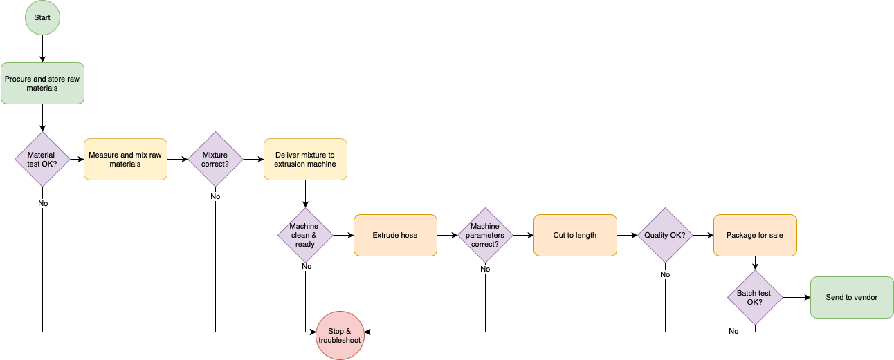
Take a company that manufactures garden hoses. They use UML diagrams to document their production processes which specify how the materials they use need to be procured, stored, processed, and the final product packaged. These diagrams would include the data that should be gathered, constraints on the machines during the production process, and how the final product should be quality tested.

All the processes, data structures, machine setups, controlling and monitoring software applications, and testing procedures would be visualised in a variety of UML diagrams. Together, they comprise the UML model of the hose production system.
This company wants to start producing flexible tubes for a new domain - medical. The overall process for producing flexible medical tubes and garden hoses is similar - purchase the raw materials, mix them appropriately, extrude the hoses with production machines, cut to length, test, package, and send to vendors or customers.
However, medical applications have more stringent requirements including constant testing. Materials must be safe for prolonged human contact. A clean room environment may be needed for production. There may be mandated software and hardware components for monitoring safety throughout the production process. And quality testing of the final product would be more rigorous - perhaps through an accredited third party.
The UML model for producing garden hoses can be abstracted into a metamodel that visualises the production of any type of flexible hose or tube, where profiles are used to specify what is needed for each domain - in this case, Garden and Medical.
- Metaclasses are the most basic elements of the hose production system - they show in a very general abstract way how a hose is manufactured.
- Stereotypes specialise metaclasses and show which packages, processes and/or data structures are modified to meet either the Garden or Medical hose production requirements.
- In the lower-level, more detailed UML diagrams, tagged values, constraints and
<<stereotype>>labels show which elements of each diagram have a stereotype applied.
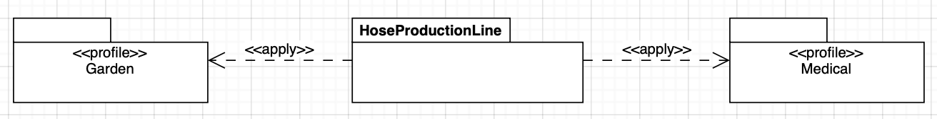
For the hose production company example described above, the following UML profile diagram abstracts their garden hose production line model and customises it for a medical domain.
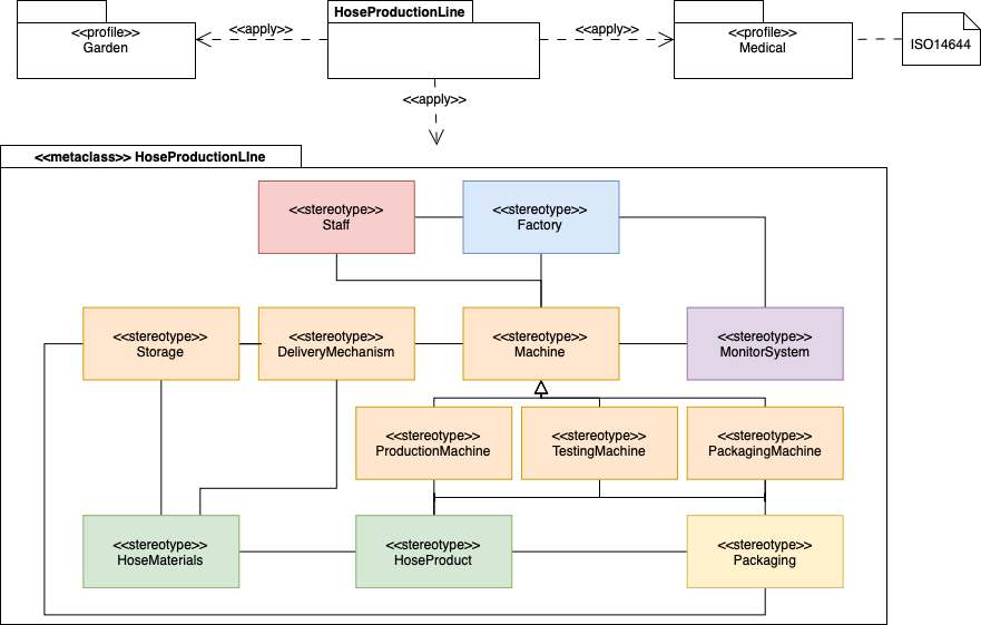
Open this example in draw.io
Elements of a UML profile diagram
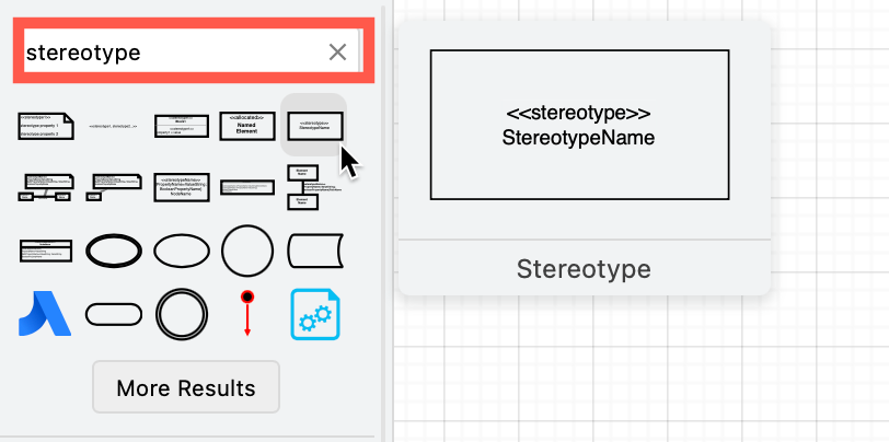
Enable the UML and SysML shape libraries
Click on More Shapes and enable the UML, UML2.5 and SysML shape libraries to see the profile diagram shapes and connectors in draw.io. Alternatively, use the search bar to quickly find stereotype, profile and metaclass shapes. Hover over any shape to see a larger preview.
Profiles
Profiles are drawn with a package shape and the <<profile>> label. An open-ended arrow on a dashed connector goes from the profile to the package or metaclass with the label <<apply>>. You can apply more than one profile to a package or class.
Metaclasses and stereotypes
Metaclasses are the foundational elements that need to be customised for each domain. In the high-level abstract, these may be simple rectangles or package shapes with a <<metaclass>> or stereotype label.
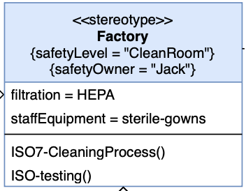
Stereotypes are classes or packages that are used to customise entities, data structures, processes, and services (meta-attributes) so they can be used in another domain. Stereotypes define tagged values and constraints that show how your system is implemented in lower level UML diagrams, ‘extending’ metaclasses.
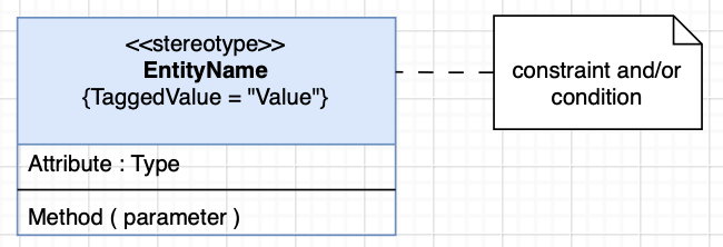
Stereotyped classes contain the <<stereotype>> label in addition to the entity’s name but may simply write the name of the entity surrounded by angle brackets: <<Garden>> or <<Medical>> when a class or package belongs solely to one profile.
Tagged values in stereotype classes
Tagged values are metaproperties in that provide additional information about the domain-specific processes and attributes, indicating how that component is used or instanced in a specific domain, or who is responsible for it. Tagged values are surrounded by curly brackets.
Constraints
Constraints define conditions or rules that apply to profiles, or to elements within a stereotype. These are written in a note shape and attached to the stereotype or profile with a dashed line.
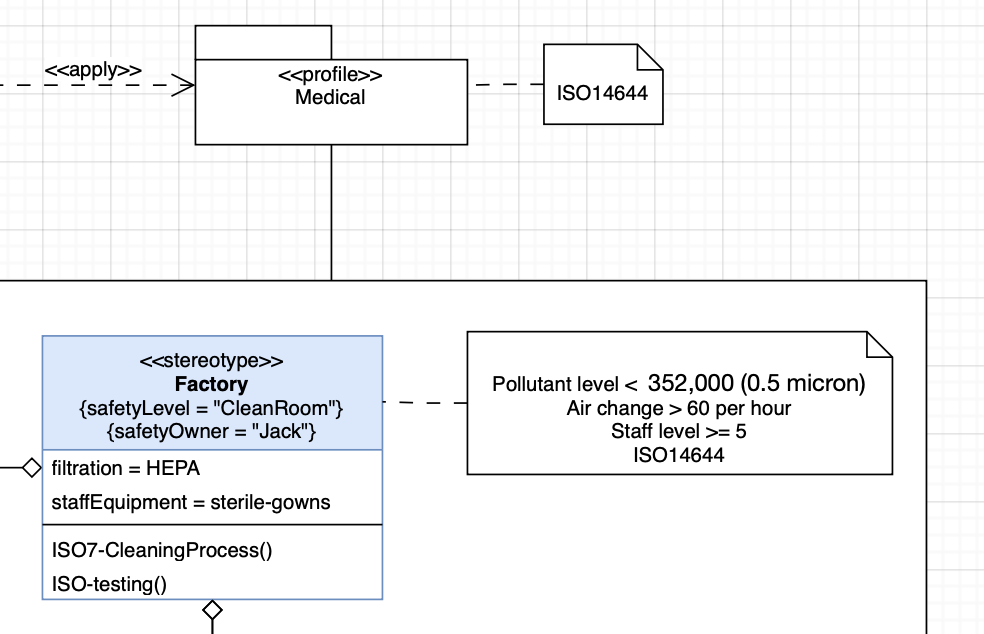
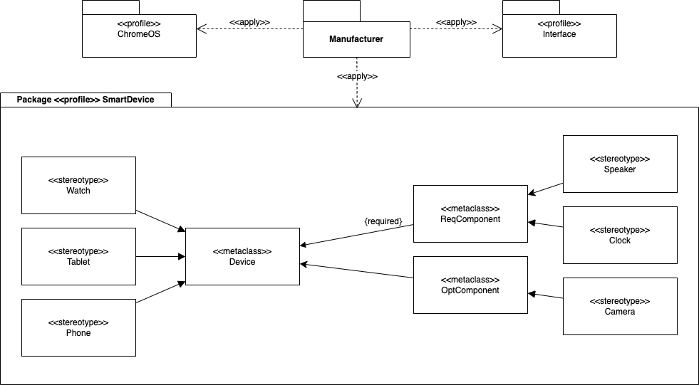
Combining profile and class diagrams
It is common to combine the profile overview with stereotype class definitions for one or more of the profiles, as in the diagram below.
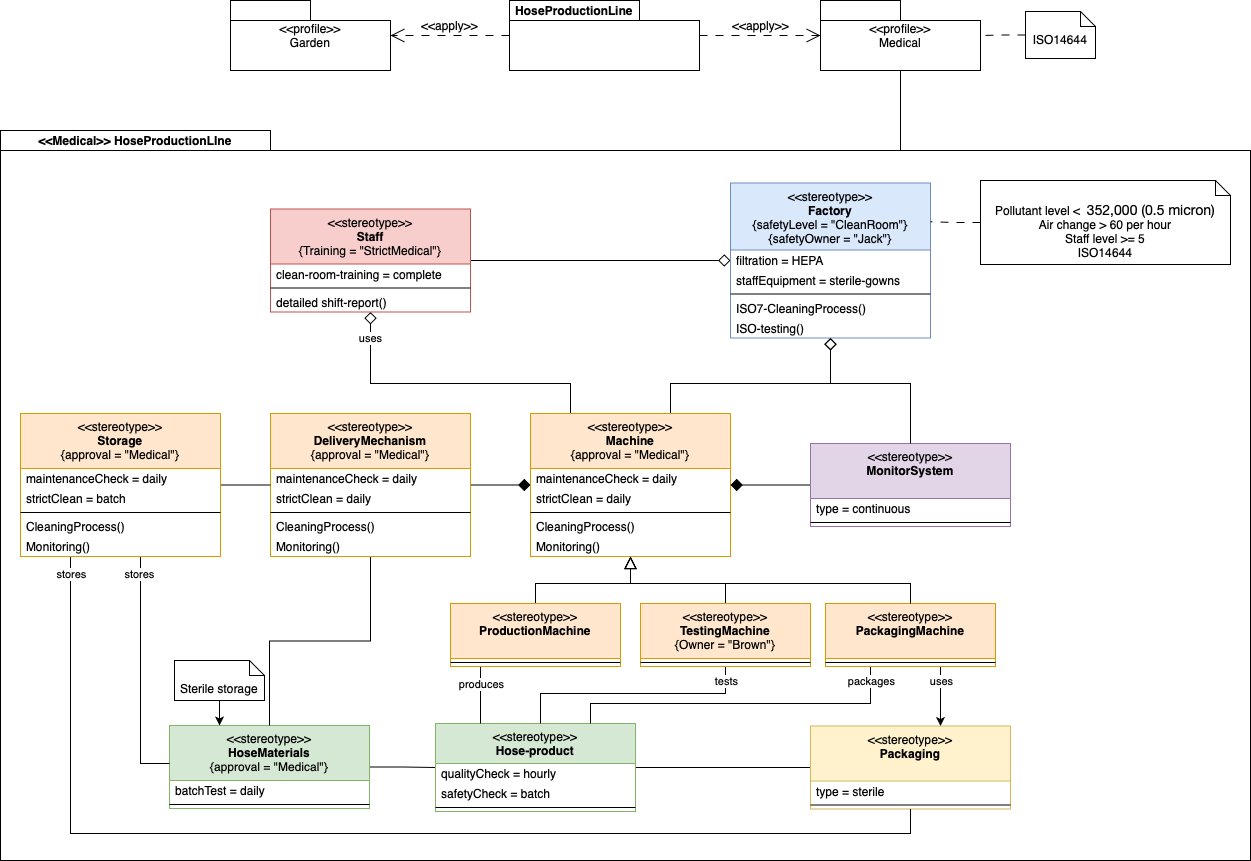
Open this example in draw.io
Other types of UML diagrams
The UML specification allows you to draw many different types of diagrams to model the behaviour and data of a system in different ways.
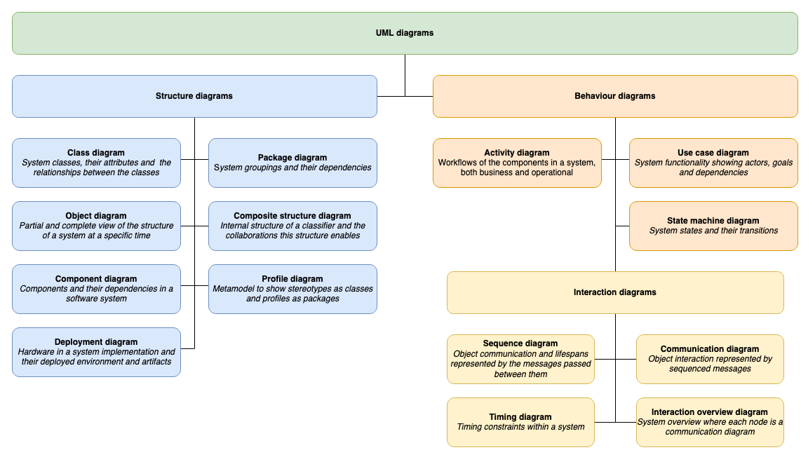
Refer to the UML diagram overview post for details of the many other types of UML diagrams.