Draw and style connectors in draw.io
Connectors are lines that connect your shapes together and may or may not have arrows at one or both ends. In a diagram, connectors provide context information, showing how the various shapes and entities in your diagram are related.
Connectors are used to group related information and systems, show flow of information and control, and specify the complex relationships between functions and systems in UML diagrams.
Tip: Connectors are also known as lines or edges. Some of the properties in draw.io that affect connectors use the term ‘edge’ when defining connector styles.
Floating and fixed connectors
There are two main types of connectors in draw.io.
Floating connectors - These move around the perimeter of your shapes as you move them around the drawing canvas, or change the route that the connector takes.
Fixed connectors - These stay attached to fixed points on your shapes, even when you move the shapes around the drawing canvas.
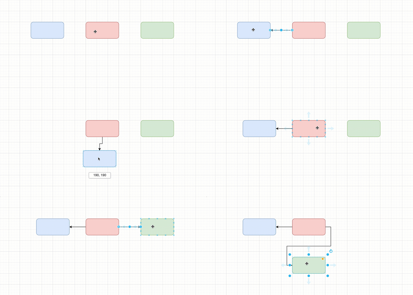
Connectors can be fixed and one end and floating at the other, or the same type of connection at both ends.
You can change a shape’s style to only allow connectors to attach to connection points. When you move the shape, the connector will snap to the nearest connection point.
Draw connectors between shapes
While there are a number of connector shapes available in the shape libraries, it is easier to draw connectors between shapes on the drawing canvas, then style them as you need.
There are several different ways you can draw connectors in draw.io.
Draw a floating connector: Hover over an existing shape, click and drag a connector from one of the four directional arrows and hover over the target shape. Drop the connector end when the shape outline is blue. You’ll see the end of the connector turn blue with a circle to indicate it’s a floating connection.
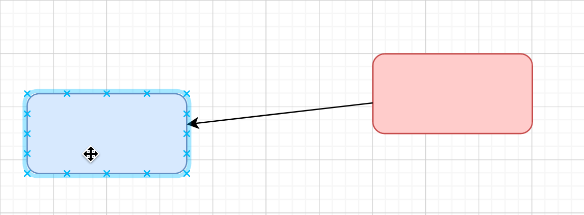
Draw a fixed connector: Hover over a shape to see the fixed connection points. Click and drag a connector from one of these points - a cross highlighted in green - and hover over the target shape. Drop the connector end over a fixed connection point when it is highlighted in green. You’ll see the end of the connector turn green with a cross to indicate it’s a fixed connection.
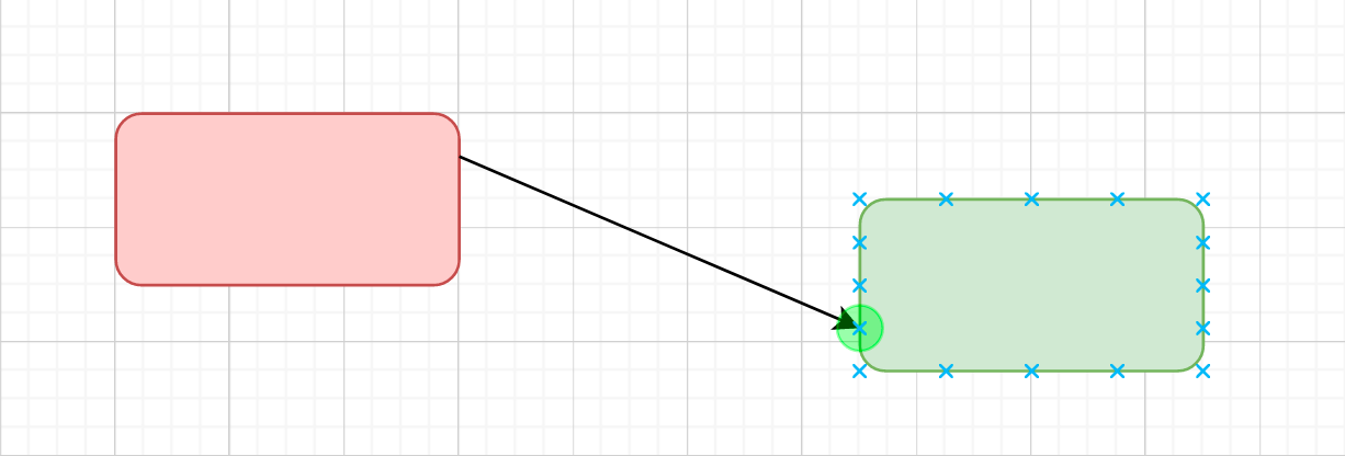
Fixed connection points are usually spaced evenly around the outside of a shape. You can override this and change a shape’s style to have custom connection points.
You can fix the end of a connection to any location within a shape: Hold down Alt as you drag the connector into position over the target shape, then drop the connector when you see a green outline on the shape (indicating a fixed connection point).
Tip: If the target shape is directly above/below or to the right/left of the source shape, hover over the source shape, then click on the arrow pointing towards the target shape to quickly connect the two.
Join connectors
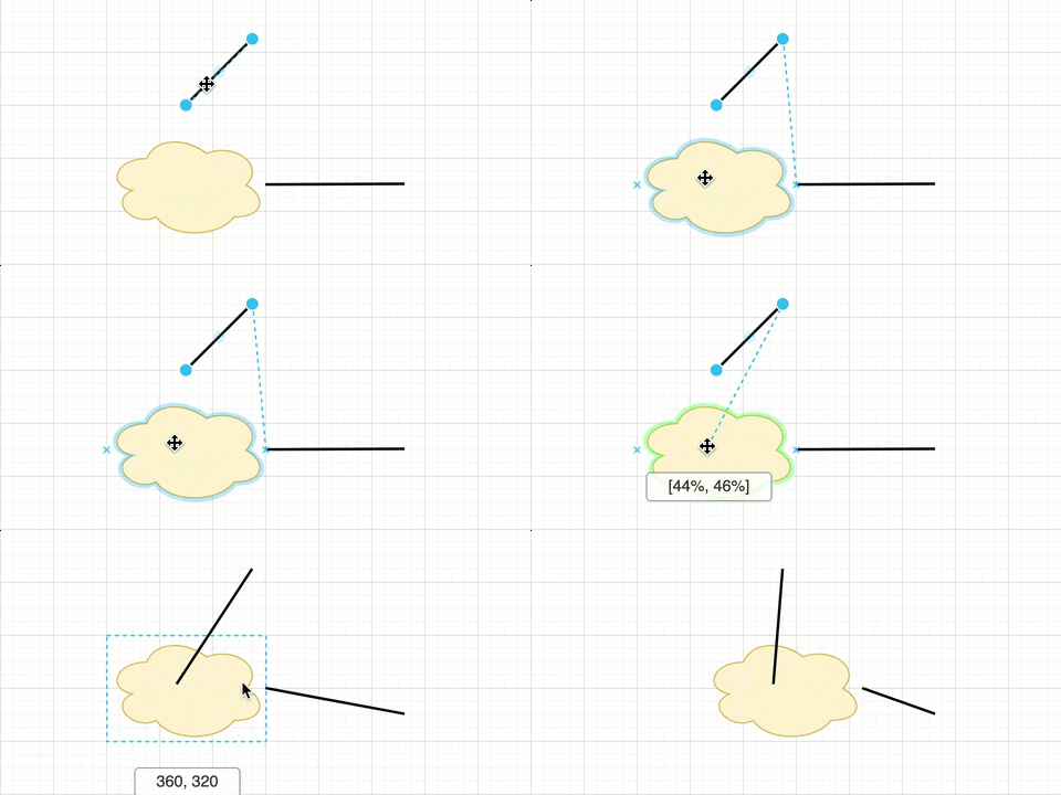
Use the waypoint shape in the Misc shape library to join connectors instead of overlapping them. Drop connectors onto or drag connectors from the waypoint shape, just as you would any other shape.
Add connectors automatically when you add a new shape
When you add new shapes to the drawing canvas, draw.io can automatically add connectors between them.
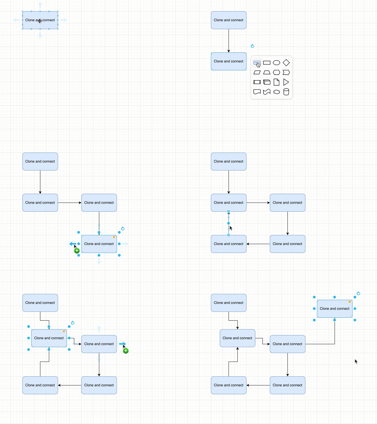
Clone and connect a shape: Hover over a shape and click on a direction arrow towards a blank space on the drawing canvas, then select a shape to add and connect it in that direction.
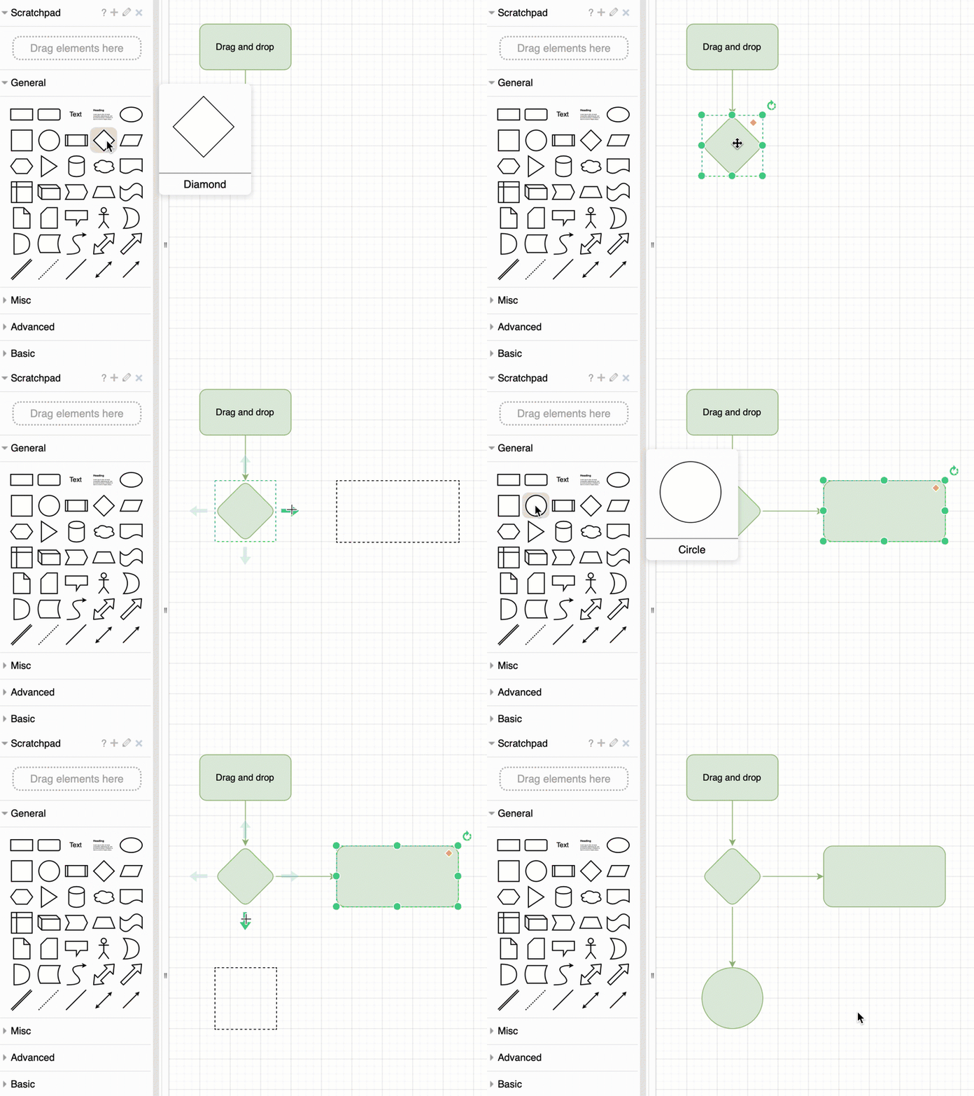
Drag and drop a shape: Drag a shape from the shape library or the drawing canvas, hover over another shape and drop it on one of the direction arrows (or an existing unconnected connector).
See how to use shortcuts to add and connect shapes, and clone and connect shapes
Add labels to a connector
Connectors can have three labels - one in the middle, and at either end.
Double click on the connector at the location where you want to add a label.
These labels will move with the connector as you move the shapes around on the drawing canvas, but you can also drag them to another location. Select the label by clicking on it, then drag the diamond grab handle to a new position.

Tip: When you reverse a connector, the labels at the source and target ends are also swapped.
Move the path of a connector
Connectors use waypoints to follow a path through your diagram.
Drag parts of the connector into a new position to make it take a different route. Waypoints are added and removed automatically as you drag them into new positions.
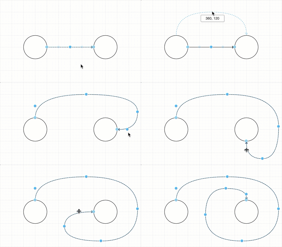
If you want to add extra waypoints manually, right-click on the connector, then select Add Waypoint from the context menu.
Learn more about working with waypoints
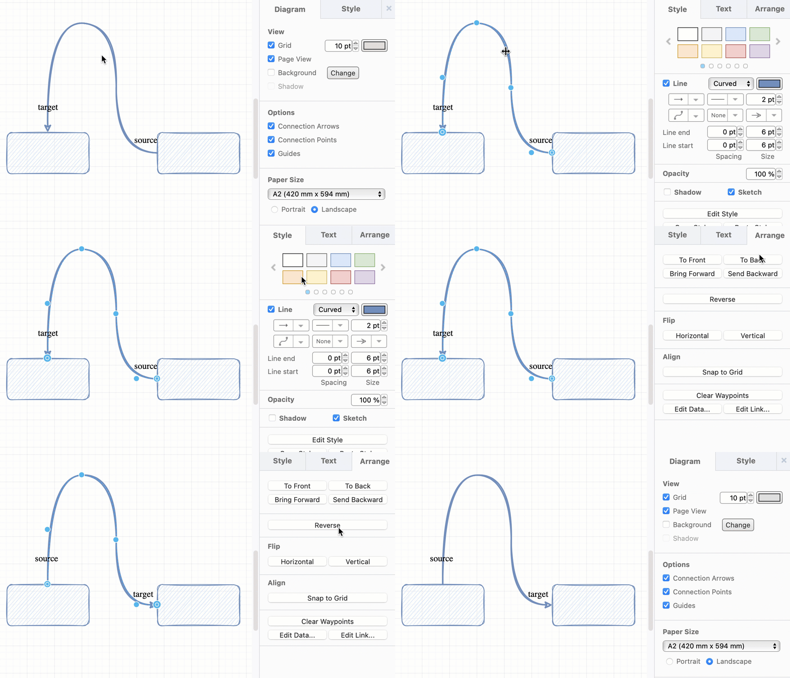
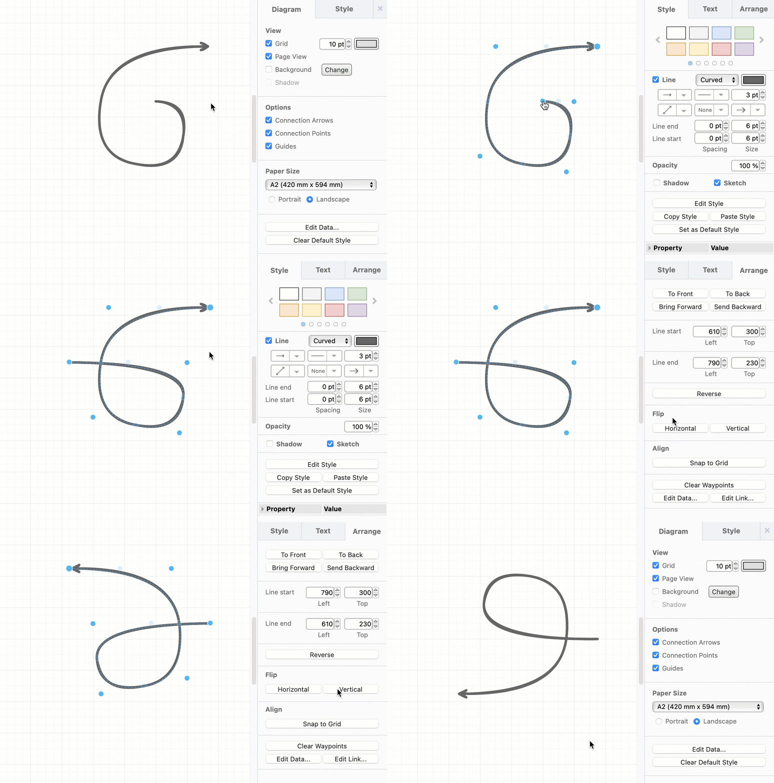
Reverse a connector: Swap the target and source ends of a connector along with their labels via the Arrange tab in the format panel.
Flip a connector: Flip a connector horizontally or vertically via the Arrange tab in the format panel. The path that a connector takes through its waypoints will be changed, which may have unintended consequences where the connector is attached to shapes.
Style connectors
The default connector style is a solid line with an arrow head at the target end.
Just like you can change a shape’s colour and outline, you can change a selected connector’s colour and line style, and set the ends of a connector to have an arrow or another symbol, using the options in the Style tab of the format panel on the right.
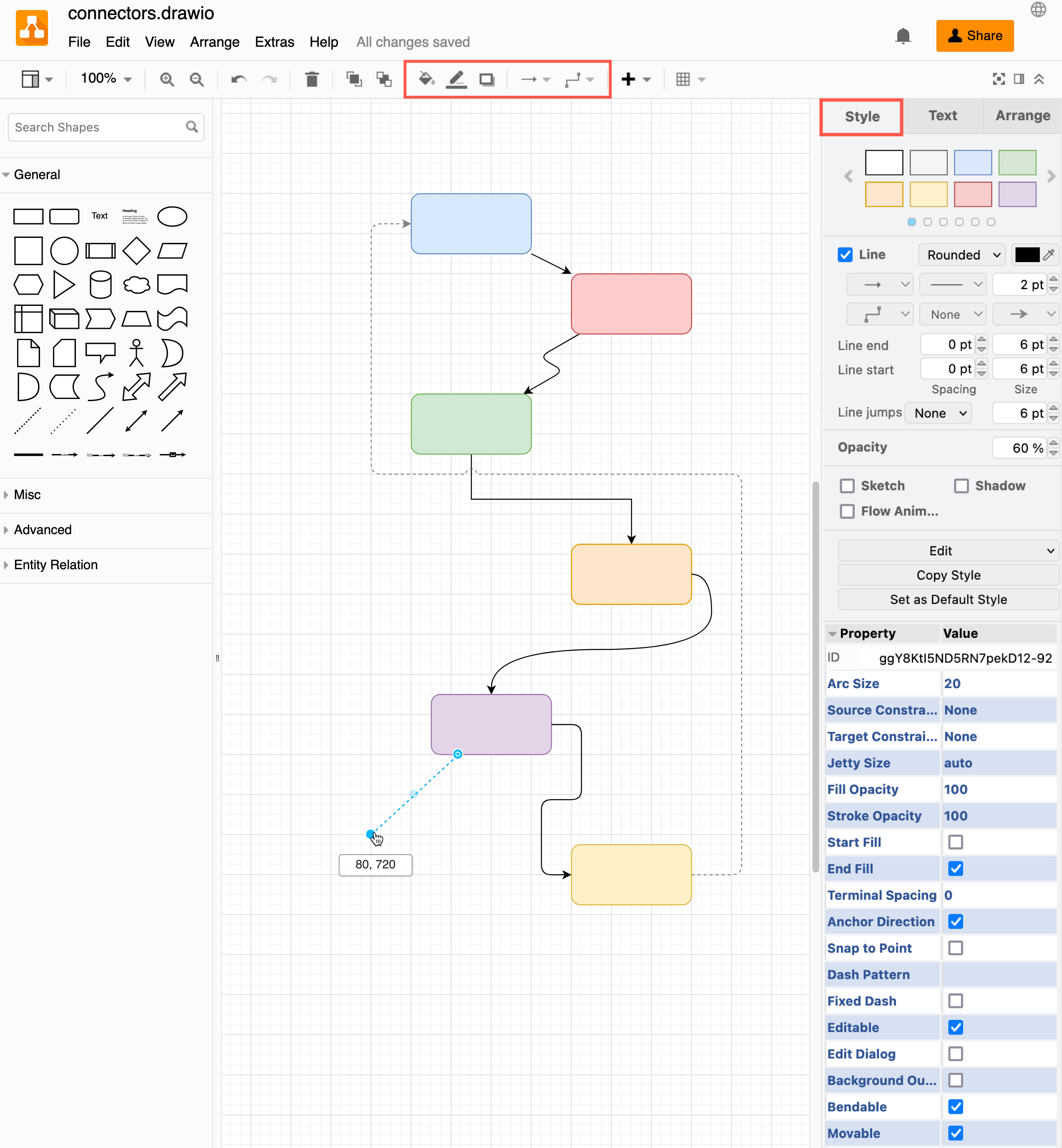
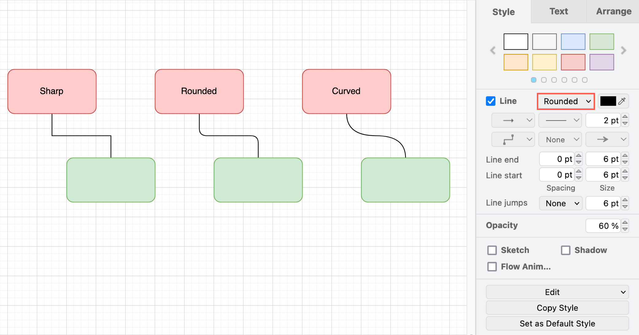
Here is how the various connector styles appear in a diagram in the editor.
Sharp/rounded/curved - this changes how the ‘bends’ in a connector appear, whether there is a sharp or slightly rounded corner when it changes direction, or a smooth curve.
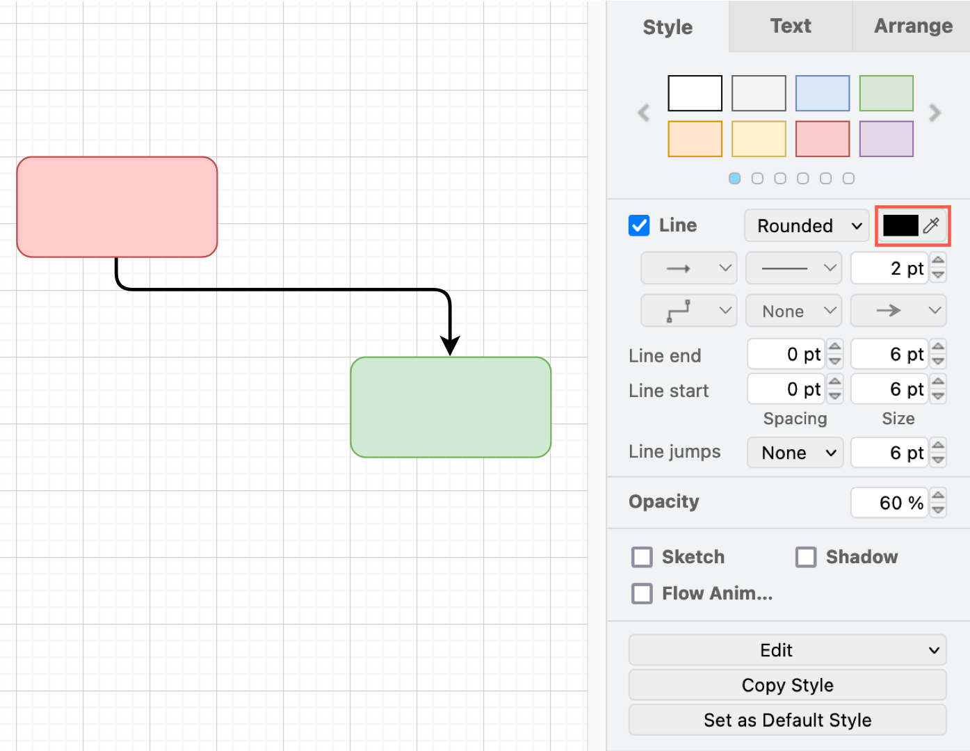
Colour - Click on the colour button next to the line style to open the palette and choose a different colour for the connector.
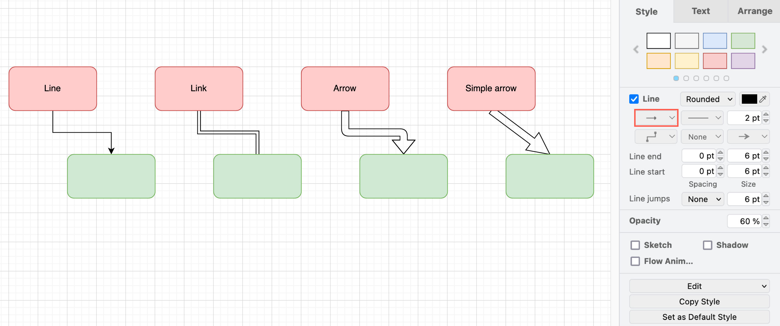
Connection - Use the top-left drop-down list to choose how the line appears - a single solid line, a double line, or two style of ‘thick’ arrows. Drag the diamond grab handles on a selected double-line connector to change the size of the gap and/or the arrow head.
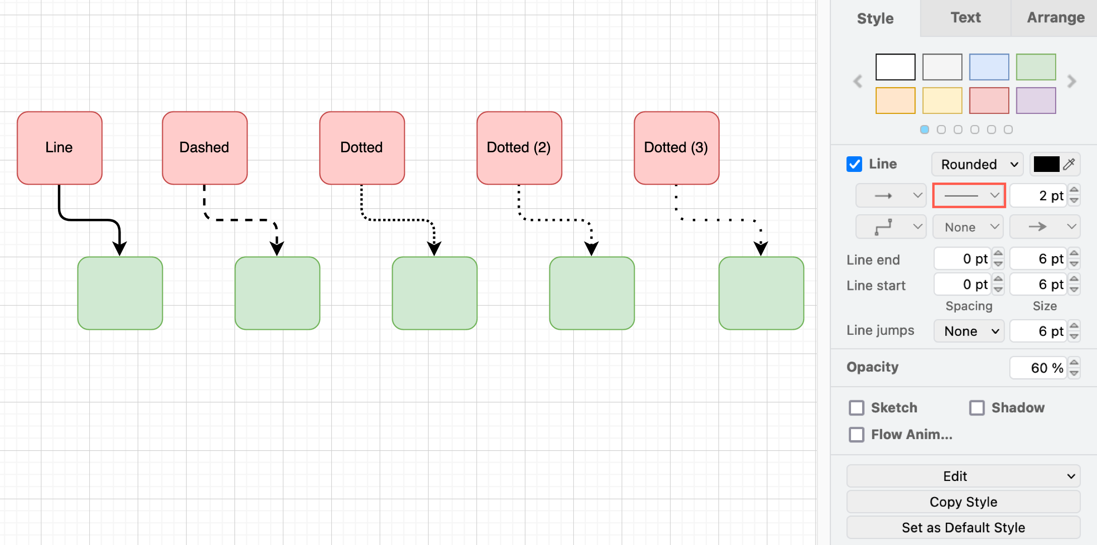
Pattern - Use the top-middle drown-down list to select a different pattern for the connector’s line/outline. Choose from solid, dashed, or dotted in various patterns.
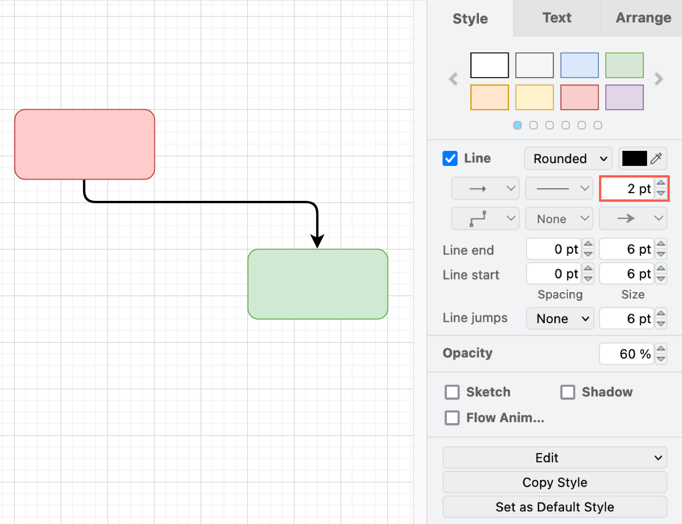
Thickness - Enter a new pt value in the textbox to change the thickness of the connector’s line/outline.
Waypoints - Select one of the predefined paths which will determine how many waypoints are added to the connector.
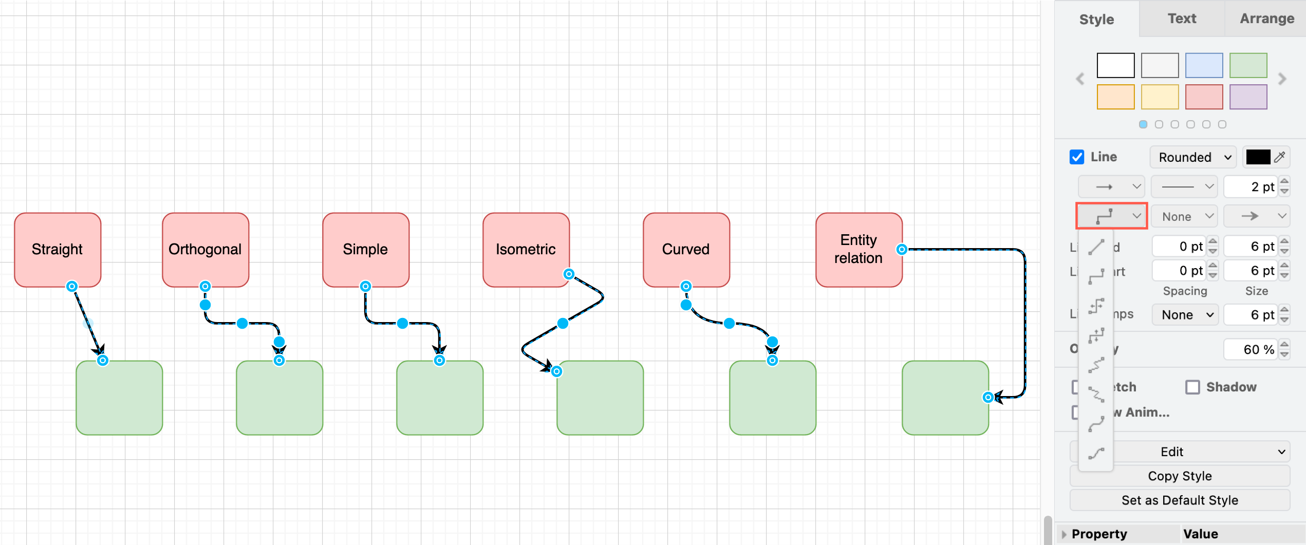
In the example above, you can see that the different styles have very different waypoints. The entity relation waypoint style always leaves the source shape and enters the target shape on the same side and has two orthogonal bends in the connector - there are no other waypoints in this style of connector.
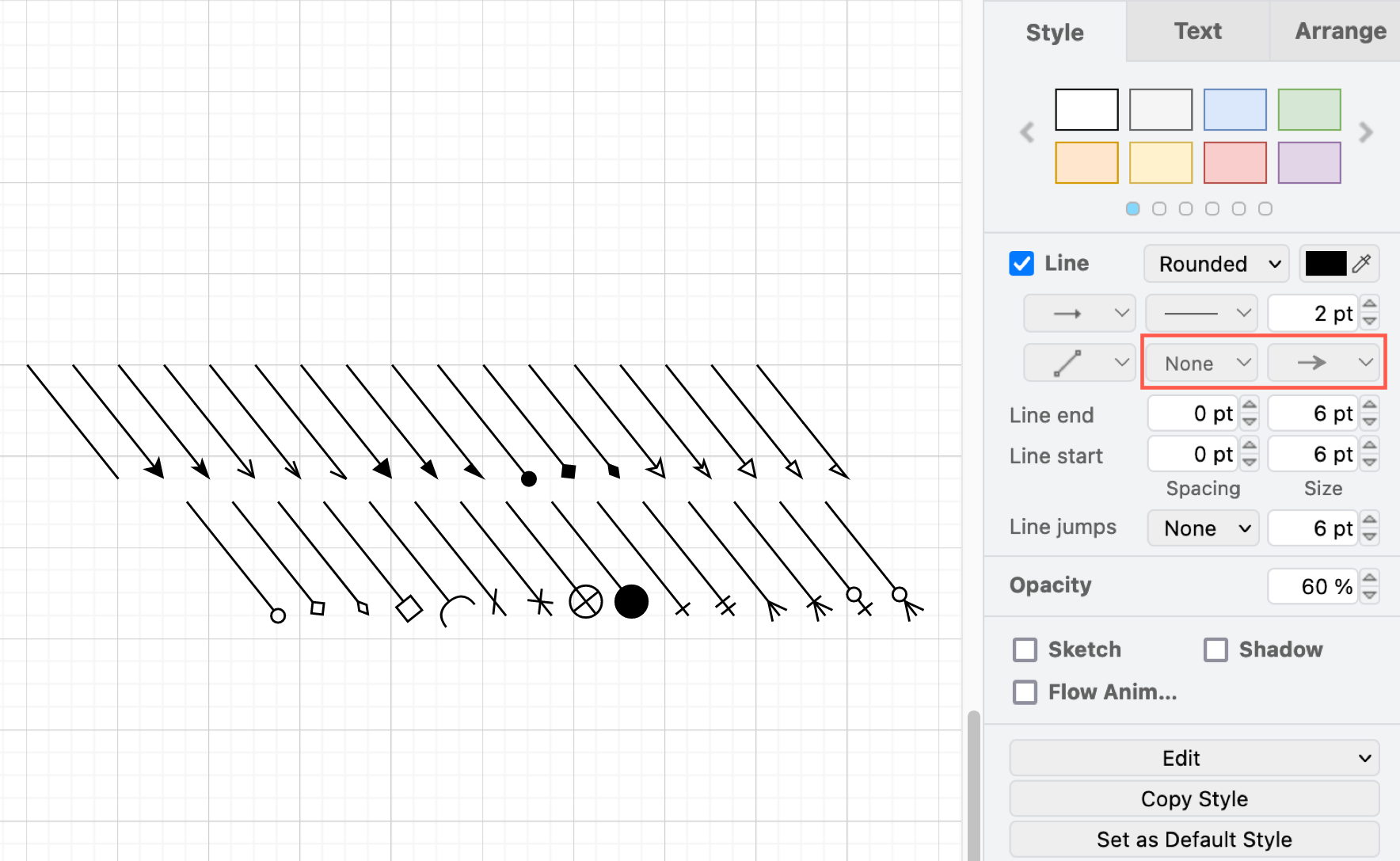
Source and target ‘arrow’ heads - Select a connector head from the very large drop down list. There are many different types of arrows and symbols. Choose None for just a plain line.
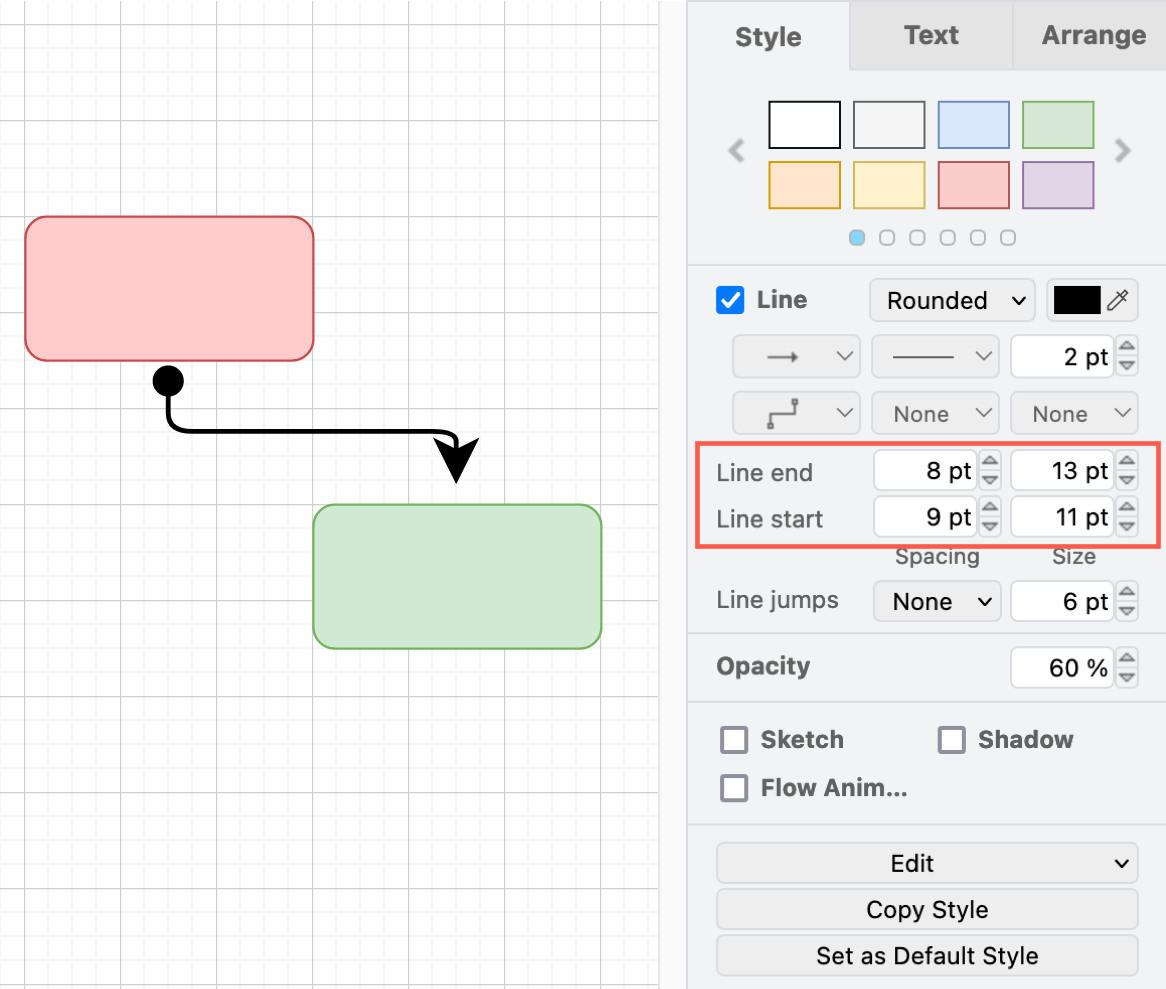
Line end and Line start - Set the size of the arrow head or symbol, and the space between it and the shape outline. Negative values for spacing will position the end of the connector inside the shape boundary.
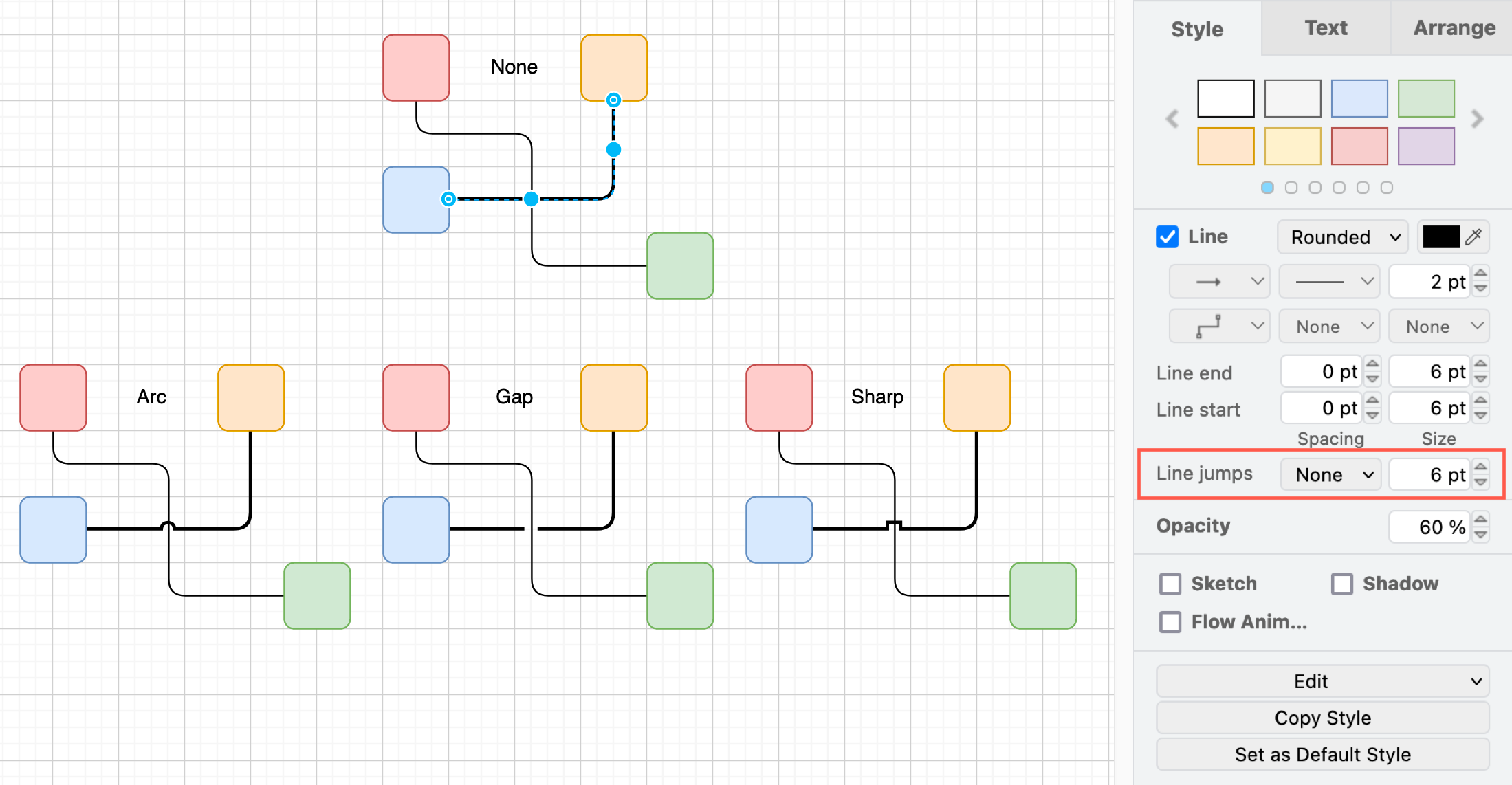
Line jumps - Choose how overlapping connectors should be displayed. Change the size of the gap by entering a new number in the text box to the right of the line jump style.
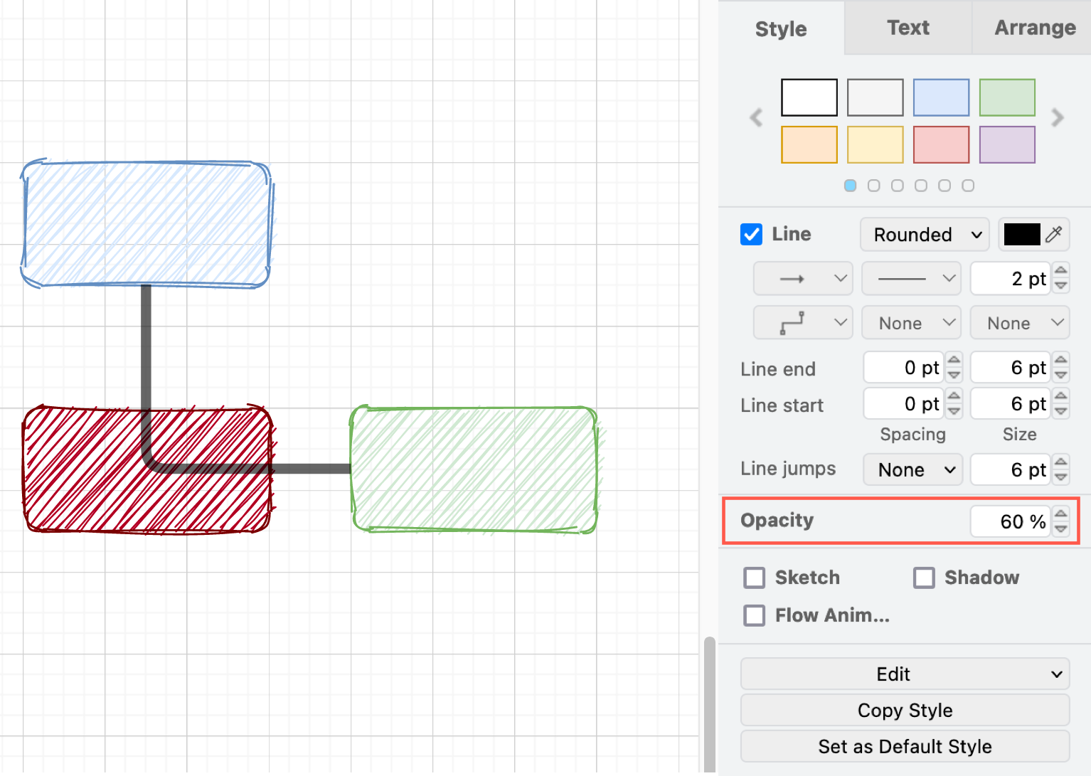
Opacity - Change the opacity percentage to let shapes and connectors that are underneath your selected connector show through.
Shadow and Sketch - Enable the checkboxes to add a shadow to your connector, or make your connector look roughly hand-drawn.
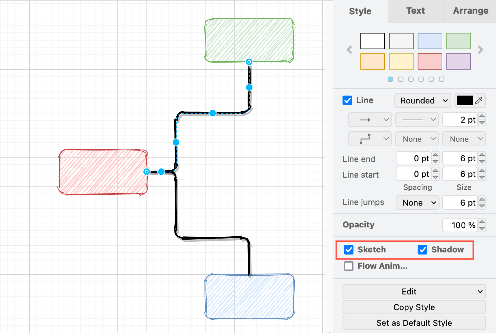
You can copy and paste connector styles just like you would shape styles using the two buttons in the Style tab of the format panel - Copy Style and Paste Style.
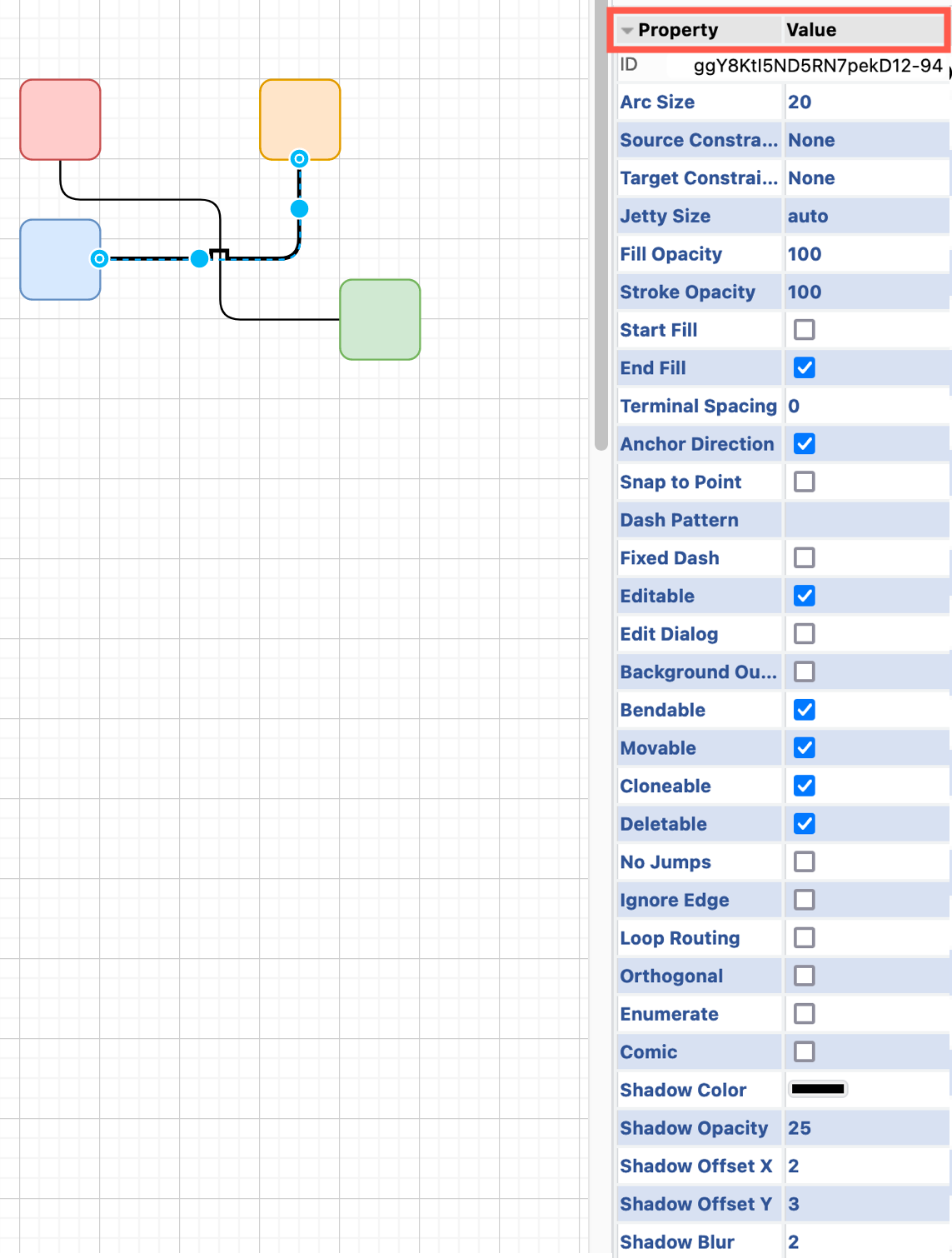
Expand the property list at the bottom of the Style tab in the format panel, to change additional connector style properties.
Manually edit a connector’s style
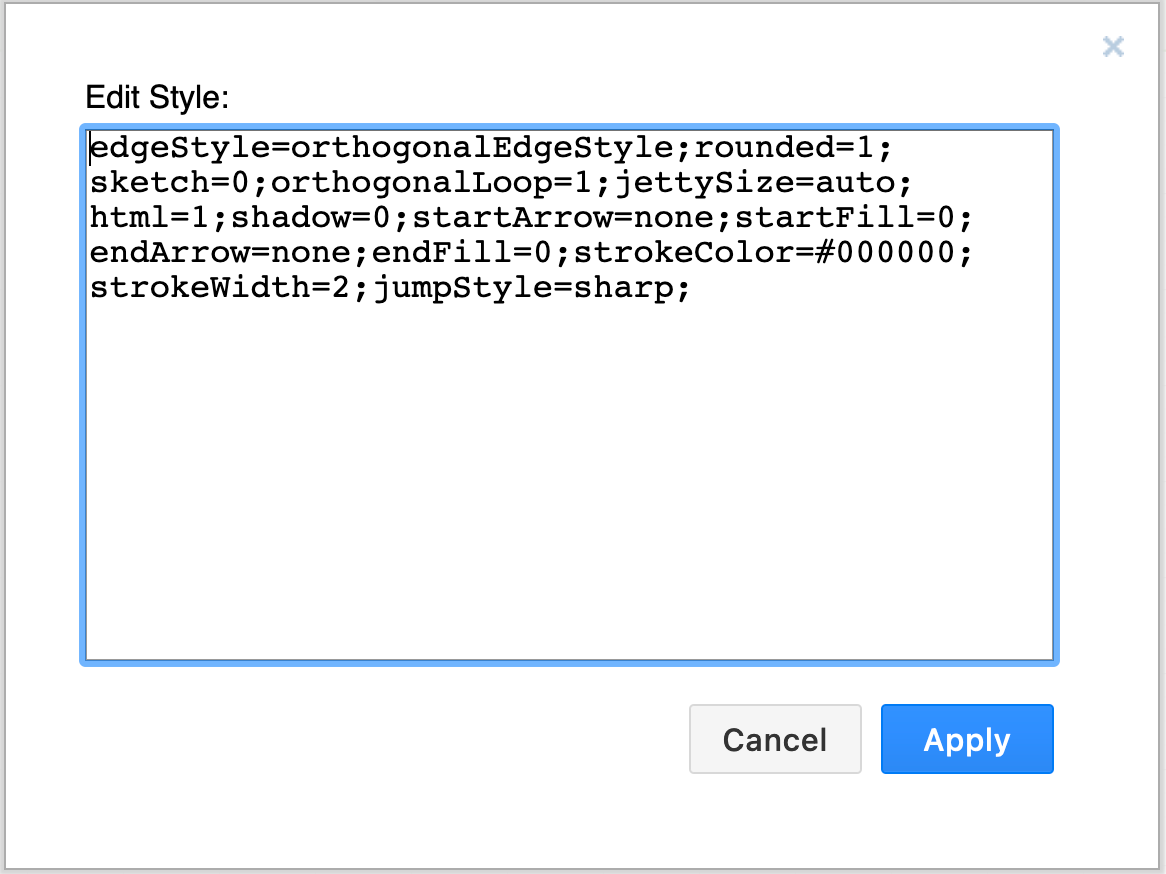
You can manually edit a connector’s style using key=value pairs.
- Right click on a connector, then select Edit Style. Alternatively select a connector then press
Ctrl+Eon Windows, orCmd+Eon macOS. - Edit the style in the textbox then click Apply to save your changes.
See all of the available styling options and learn how to set a default style for the diagram editor