Use PlantUML in draw.io
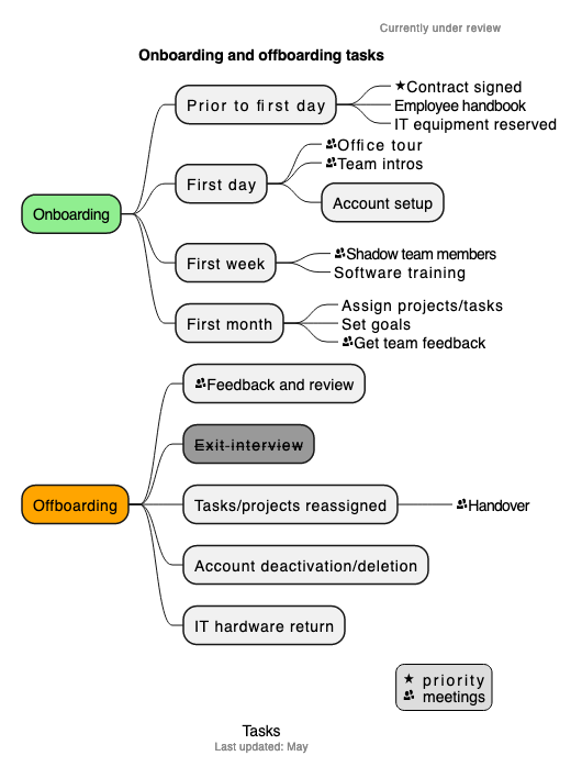
With PlantUML in draw.io using our web application (app.diagrams.net) you can quickly draw UML diagrams from a text description. When you input your PlantUML text, the diagram editor will automatically layout and arrange the diagram for you, based on your description and the style of output you select. It supports many different types of UML diagrams, as well as mindmaps, tree diagrams, flowcharts, network diagrams, Gantt charts, ER diagrams and more.

Tip: You can generate PlantUML from code with some software development tools. PlantUML functionality in only available in online versions of draw.io, not draw.io Desktop or draw.io for Confluence/Jira DC, for example.
Learn more about generating diagrams from code.
Insert a PlantUML diagram
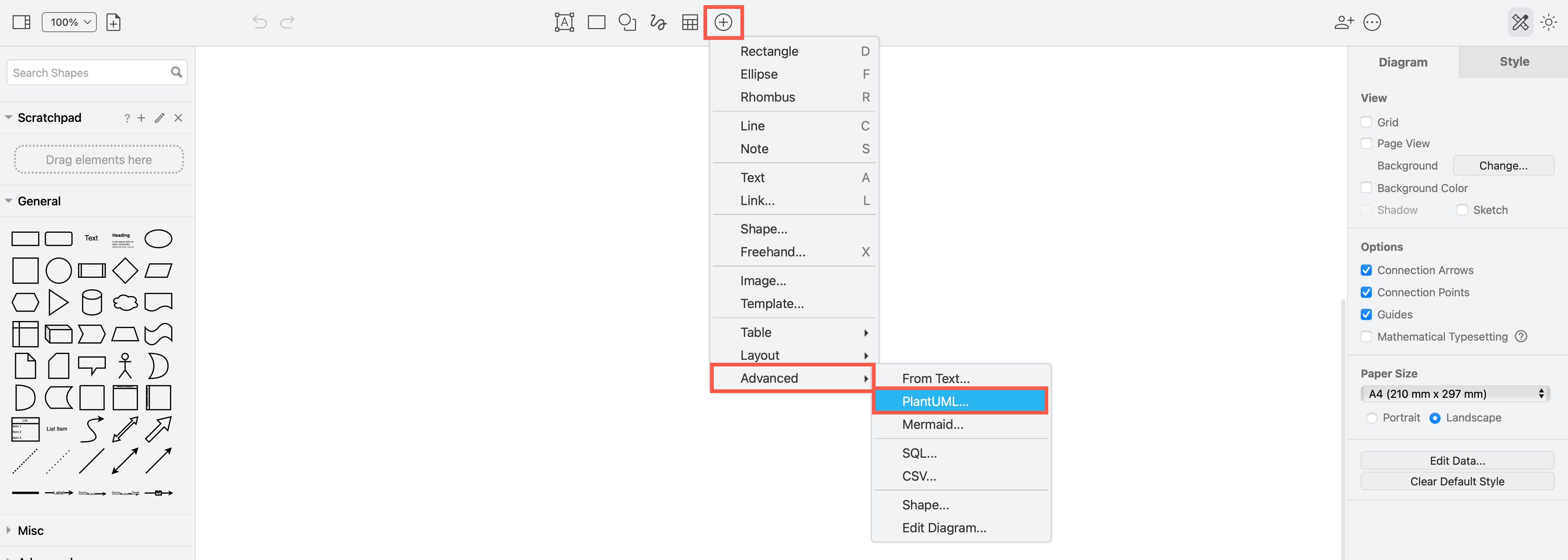
- Click on the plus in the toolbar, then select Advanced > PlantUML in the simple editor mode and the Sketch whiteboard editor theme. In the draw.io editor, select Arrange > Insert > Advanced > PlantUML from the menu.
- Enter the PlantUML in the text field.
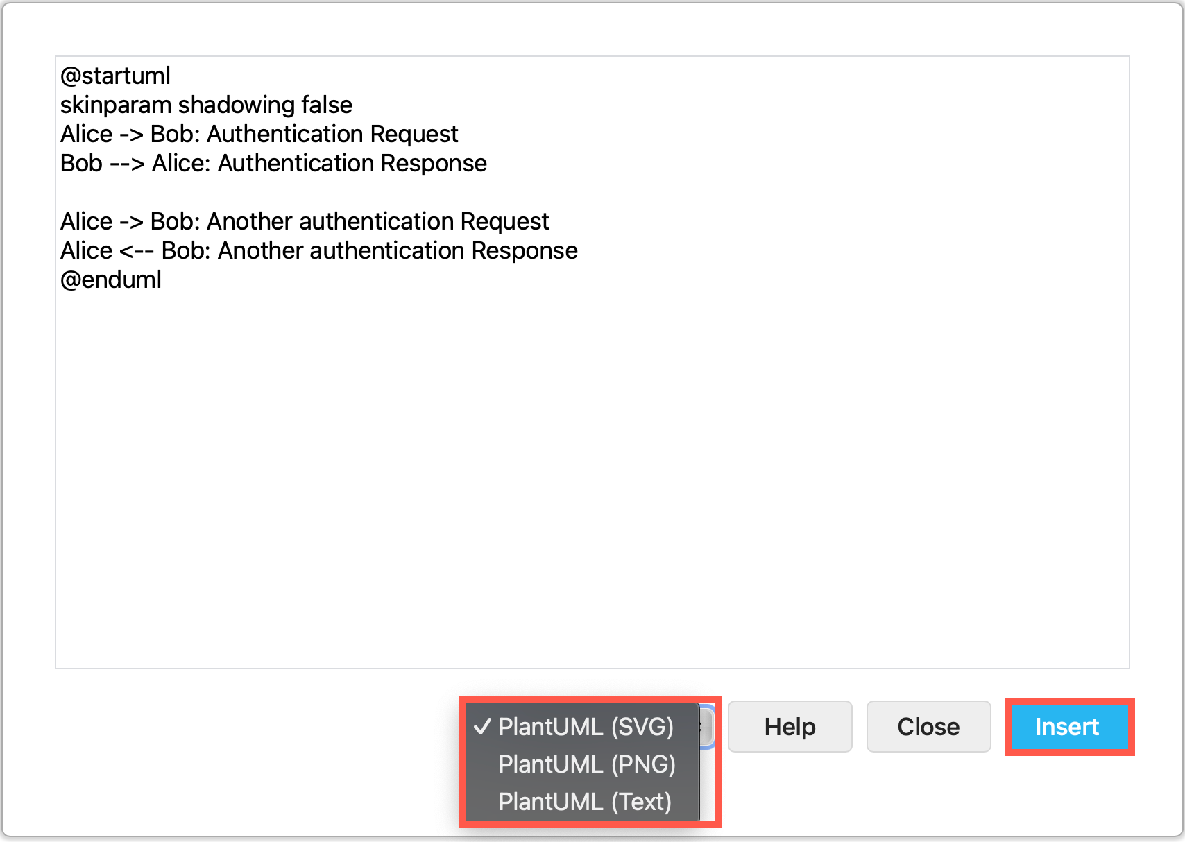
- Select the output format you want (SVG, PNG or Text) and click Insert.
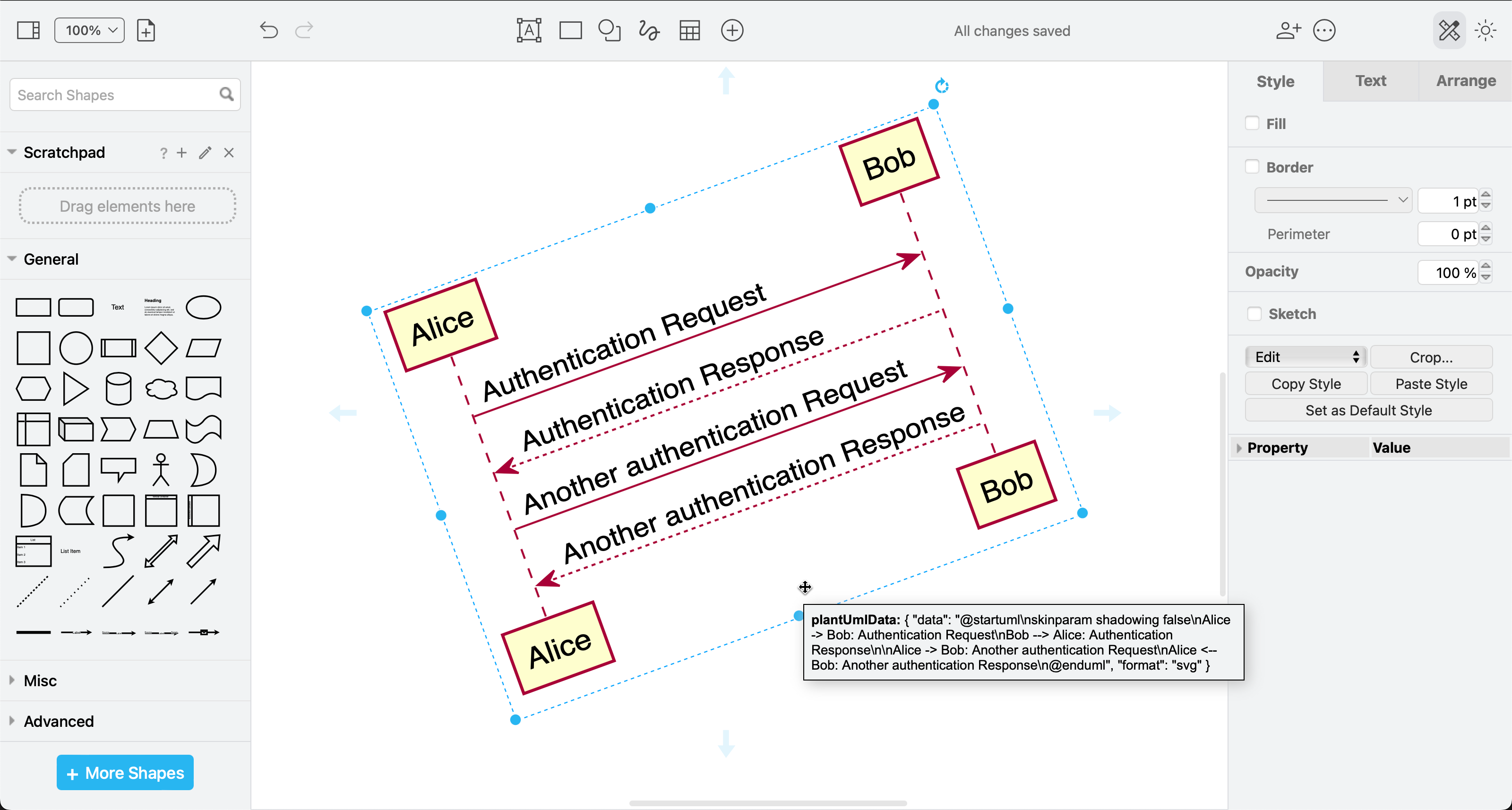
Your diagram will be generated and placed on the drawing canvas as an image shape. You can resize and rotate this image and attach connectors to its outside border, but you can’t edit the individual shapes.
-
Hover over the diagram on the drawing canvas to see the PlantUML text in a tooltip.
-
Double click on the PlantUML diagram to edit the text description and click Apply to regenerate the diagram.
Style PlantUML diagrams
The skinparam key-value pairs are often used to add styles to shapes, text and connectors. You can also add icons, AsciiMath, links and tooltips.
Refer to the official PlantUML documentation for details.
Example PlantUML diagrams
UML sequence diagram
@startuml
actor User
User -> Sales: ProcessOrder
  activate Sales #FFBBBB
  Sales -> Warehouse: << packOrder >>
    activate Warehouse #gold
    Warehouse -> Picker: GetProducts
      activate Picker #005500
      Picker --> Warehouse: ProductsCollected
      deactivate Picker
    Warehouse --> Sales: OrderPacked
    deactivate Warehouse
  Sales -> Sales: SendOrder
  Sales -> User: OrderSent
  deactivate Sales
@enduml
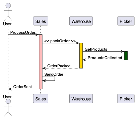
Learn more about UML sequence diagrams
UML use case diagram
@startuml
left to right direction
skinparam packageStyle rectangle
actor User
actor Sales
rectangle order {
  User --> (checkout)
  (checkout) .> (payment) : include
  (order) .> (checkout) : extends (checkout)
  (order) <-- Sales
}
note "Requires login" as N2
  (checkout) .. N2
  N2 .. (payment)
@enduml
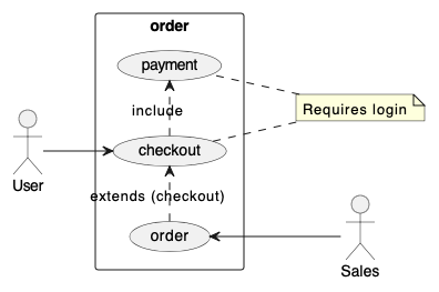
Learn more about UML use case diagrams
UML activity diagrams and flowcharts
The PlantUML syntax for writing Activity diagrams has changed over the years. It is now much more flexible, and can include swimlanes for better task separation.
@startuml
|#lightblue|Customer|
start
:Find Barista;
|#antiquewhite|Barista|
:Greet Customer;
|Customer|
:Request latte;
|Barista|
:Write details on cup;
|Customer|
:Buy latte;
|Barista|
if (Payment Accepted?) then (yes)
#lightgreen:Make latte;
else (no)
#pink:Apologise;
endif
|Customer|
:Drink latte;
note right
  //Feel perky//
end note
stop
@enduml
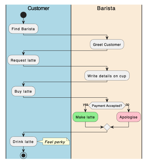
Learn more about UML activity diagrams
UML timing diagrams
@startuml
robust "Browser" as WB
concise "User" as WU
@0
WU is Idle
WB is Idle
@+100
WU -> WB : URL
WU is Waiting
WB is Processing
@+200
WB is Waiting

@enduml
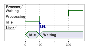
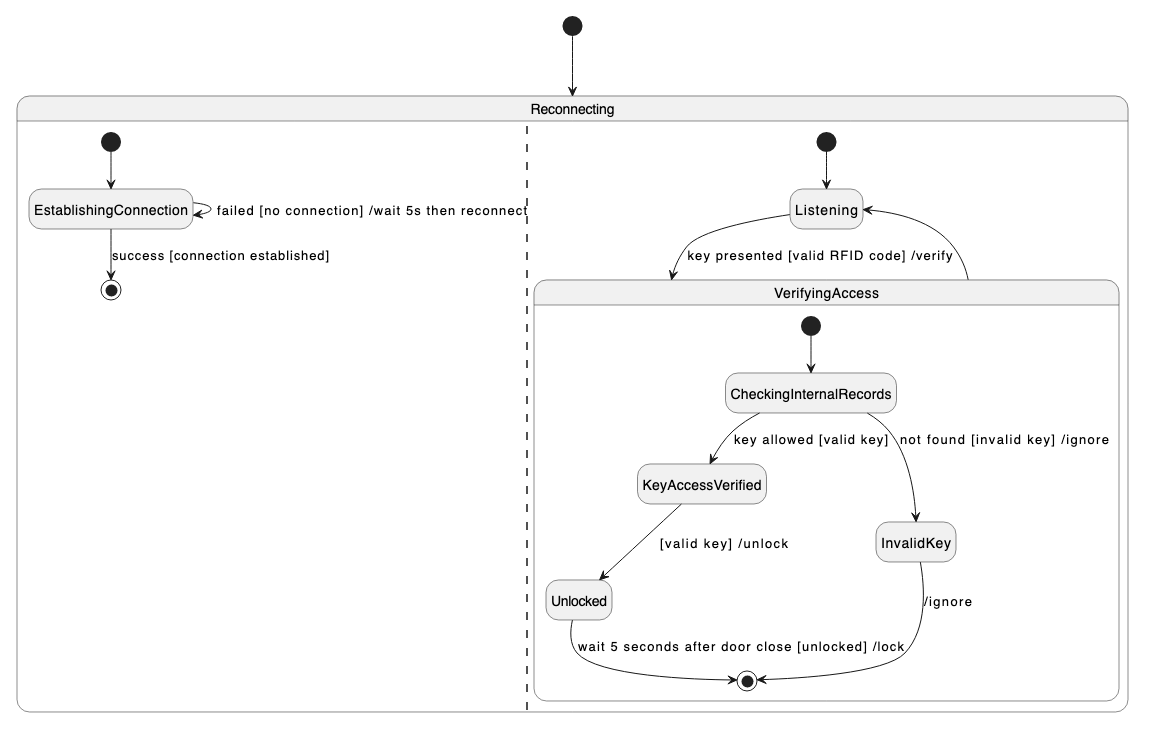
UML state machine diagram
For the PlantUML text description of this example, please see our article about state machine diagrams.
Non-UML diagram examples
Gantt chart
@startgantt
  [Design] lasts 5 days
  [Tests] lasts 5 days
  [Production system programming] lasts 20 days

  [Tests] starts at [Design]'s end
  [Production system programming] starts at [Design]'s end

  [Design] is 100% complete
  [Tests] is 50% complete
  [Production system programming] is 5% complete
@endgantt

Concept maps and tree diagrams
PlantUML uses the Graphviz/DOT language for non-UML diagrams.
@startuml
digraph UMLdiagrams {
edge [arrowhead=none]
node [style=rounded]
 UML -> Structure [color=lightblue];
 UML -> Behavior [color=orange];
   Structure -> {Class Package Object CompositeStructure Component Profile Deployment} [color=lightblue];
   Behavior -> {Activity UseCase StateMachine Interaction} [color=orange];
     Interaction -> {Sequence Communication Timing InteractionOverview} [color=gold];}
@enduml

Mindmaps
See our earlier article about creating mindmaps from text for the PlantUML text description of this example.
