Create C4 models and diagrams
The C4 modelling is used to describe and define architectures in an abstract and simple way. Designed by Simon Brown, C4 is a different way to approach modelling software development which focuses on four c’s: context (people), containers, components, and code.
draw.io provides you with a C4 shape library with the shapes you need to create all of these diagrams, including extensive UML shape libraries for the detailed diagrams typically used at the code level. Labels are added to these shapes using metadata.
C4 model diagrams capture the three levels of design that are needed when crafting any general software or business system. The first diagram is a high-level abstract overview of your system, stepping into more detail at each level, with the fourth level typically reserved for implementation details.
Shapes used in C4 notation
The C4 notation is very simple compared to other modelling notations. It is recommended that on any C4 diagram, you include a legend of which shapes are used to represent each element.
- Person
- Software system
- Container
- Component
- Relationship - use the standard connectors in draw.io
C4 shape library in draw.io
The following shapes are available in the C4 shape library.
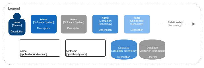
Enable the C4 shape library
- Click More Shapes in the left panel.
- Select the C4 shape library in the Software section, then click Apply.
Alternatively, create a new C4 diagram immediately in our free online editor using the following link: https://app.diagrams.net/?libs=c4
Tip: To show systems that are outside the scope of your software, change their style in the format panel.
Edit the C4 shape
- Once you’ve added the shape to the drawing canvas, double click on it to open the shape’s metadata.
- Enter the details as indicated in the text fields, then click Apply.
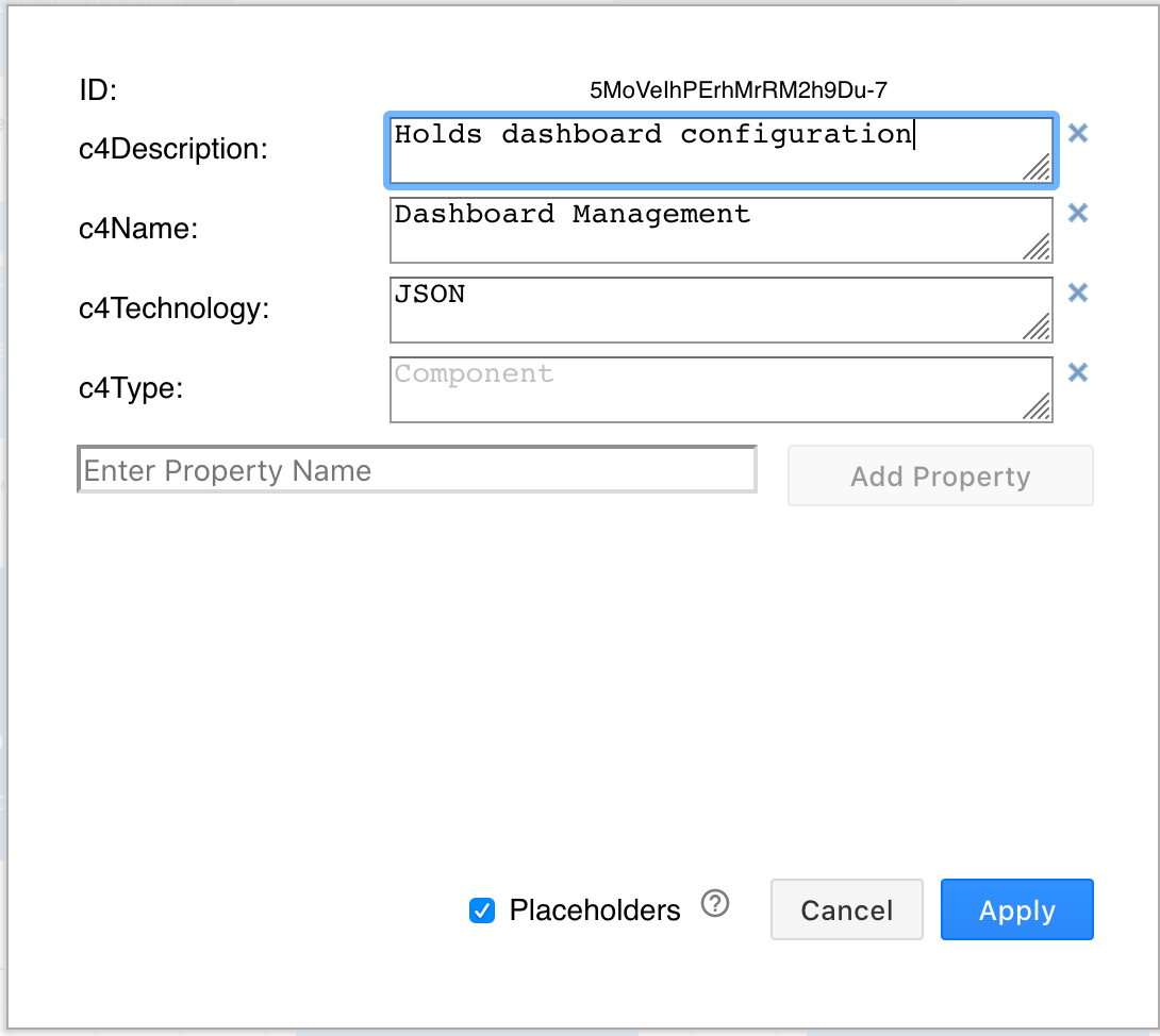
When you hover over each shape in the draw.io editor or viewer, a tooltip will show you this metadata.
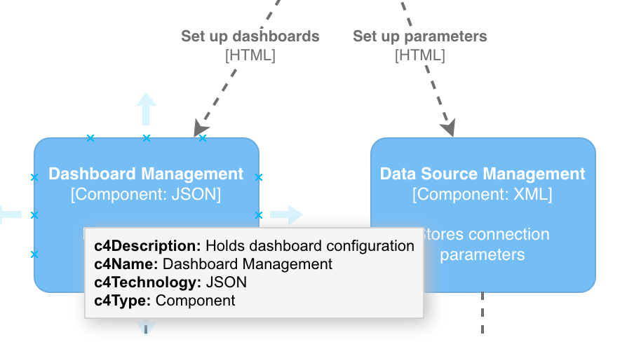
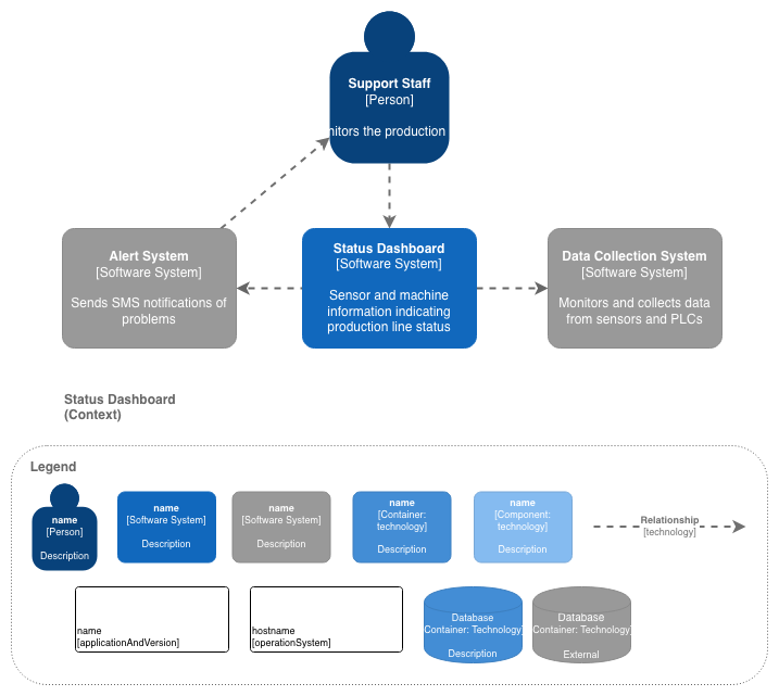
C4 system context diagram
This top-level diagram is also the most abstract. C4 system context diagrams show the big picture, how users interact with your software system as a whole, and how your software fits together with other existing software systems. These are good diagrams for showing what is in the scope of your software project, and what lies outside that scope.
Open this example context diagram in the draw.io editor
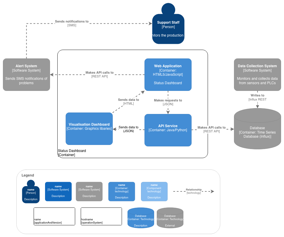
C4 container diagram
Representing the high-level technology choices, C4 container diagrams show the big elements in your software - web and desktop applications, mobile apps, databases, file systems, etc. A container is a standalone piece of software in your system that executes code or stores data. This diagram is a useful design document for software engineers and IT support.
Open this example container diagram in the draw.io editor
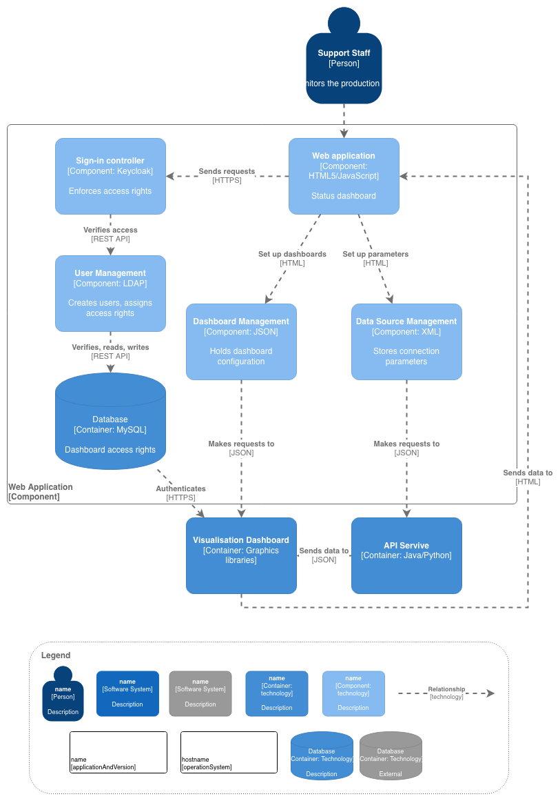
C4 component diagram
Simpler than their UML counterparts, C4 component diagrams provide more detail about each container in your system, showing what elements or components they are made up of and how they interact, occasionally with implementation details for software architects and developers.
Open this example component diagram in the draw.io editor
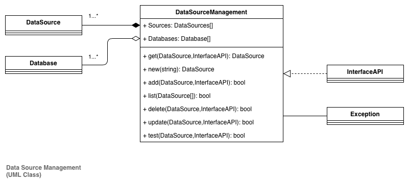
C4 class diagram (UML)
Representing the actual implementation details, UML class diagrams, entity relationship diagrams and others from the UML set of diagrams are used in the final level of C4 modelling. Often, these diagrams can be automatically created from code in a development environment, or described quickly in text form using systems like Mermaid.js (which can be imported into draw.io).
Open this example UML class diagram in the draw.io editor
Extend your C4 models in draw.io
Several features in draw.io make it more convenient to view layered diagrams such as those used in C4 models, and extend them with supplementary diagrams.
- Multi-page diagrams: Keep all of the related diagrams together in one file.
- Links between pages: Add a link to each system, container and component shape which jumps to the appropriate page in your diagram.
- UML, infrastructure and other shape libraries: If you want to go into more detail at the implementation level with UML or network diagrams, or supporting diagrams such as threat modelling you can use the many other shape libraries available in draw.io.
- Use smart labels and placeholders: For advanced diagrammers, you can define placeholder styles that can automatically style shapes as in-scope or out-of-scope.
