Case study - Requirements flows for a new website
When you contract an external company to create a website, a mobile app or a program interface, you need to provide clear requirements - user interface specifications and mock-ups, user flows and use cases, as well as data structures and note the various rules that must be followed. You could draw a set of technical diagrams for each context, or you could put it all into one diagram.
Part flowchart, mockup and data - documenting the requirements of a website
Why would you create such a complex technical diagram?
By keeping all of the visual documentation about your system and process in one file, even if it is spread over multiple diagram pages, you can more easily ensure consistency in the one comprehensive file. There is no chance of a separate but important document being forgotten or lost.
It is also easier for both your company and the external partner to ask and answer questions - you will both be referring to the one file.
Draw the website requirements
Design a website to provide downloads for licensed software and trial requests
An engineer who normally uses draw.io for data-driven dashboards was tasked with documenting the requirements of a new part of the company website. An external development company will be contracted to create this section of the website, as its complexity was beyond in-house capabilities.
This section of the website will provide registered users with access to downloads of trial and purchased software programs.
- Users could be either private users or a member of a company account.
- Companies (and team managers) could allow purchased software to be downloaded by all their staff, or only by certain teams, and allow individual staff members to request a trial of another software product.
- However, all trial licenses requested by any type of user must be manually reviewed and approved internally before a download is offered.
Part flowchart and part mock-up - the sign-in and sign-up process and rules
Note: This engineer is neither a technical documentation expert nor an artistic designer - very few people who need to draw and read technical diagrams are. If you don’t need to use a specific technical diagramming standard like BPMN or UML, your diagram is good enough when it is readable, unambiguous, and easy to navigate.
Draw an overview requirements flow
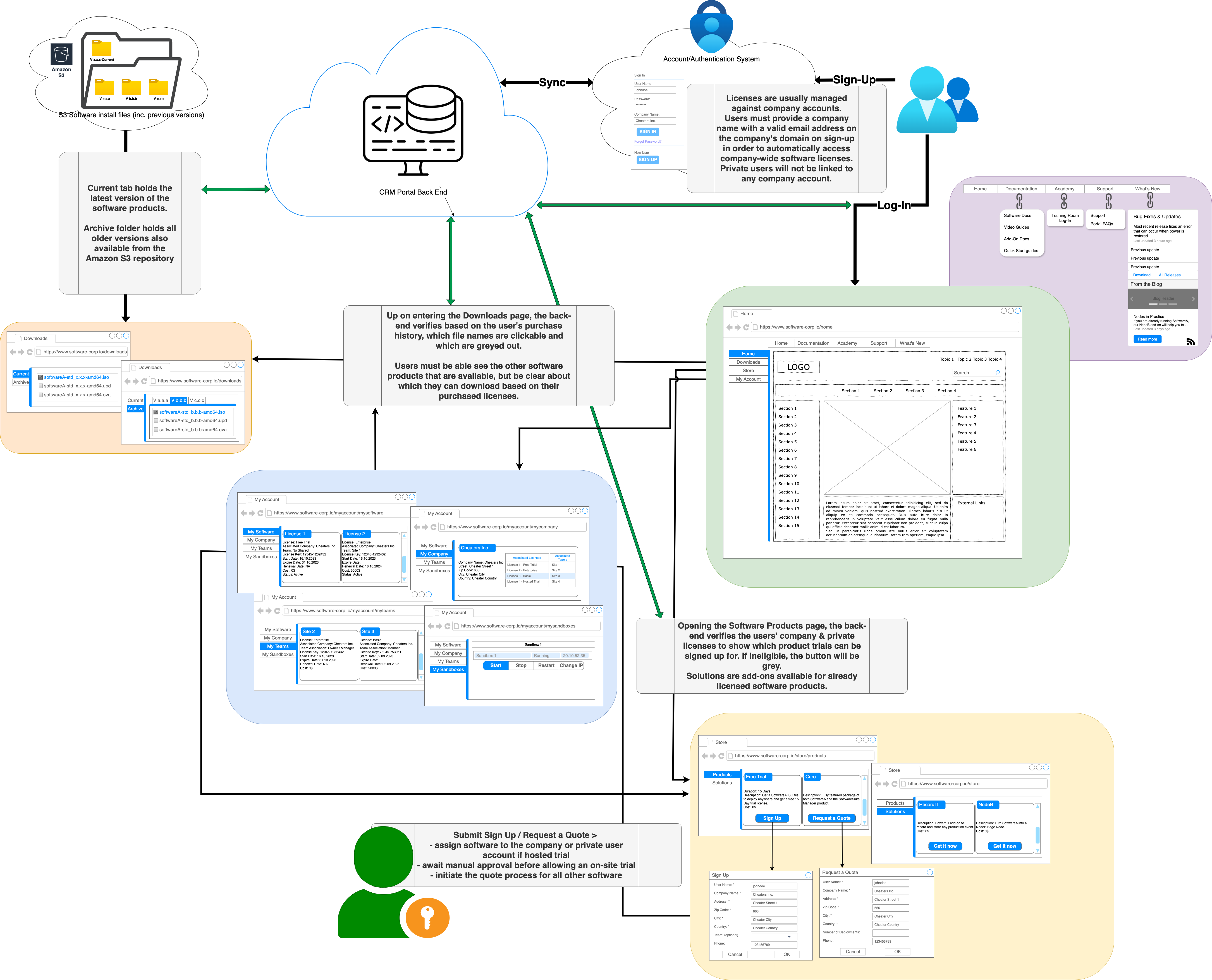
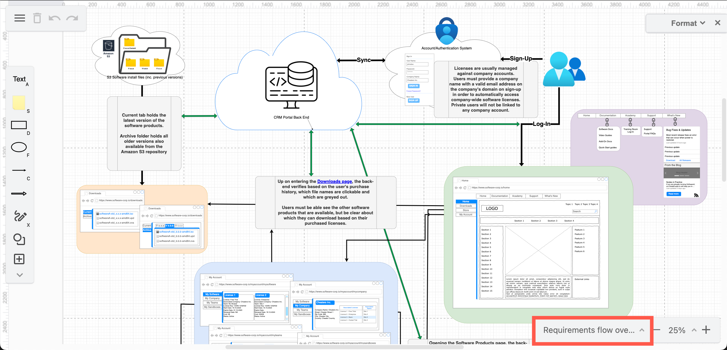
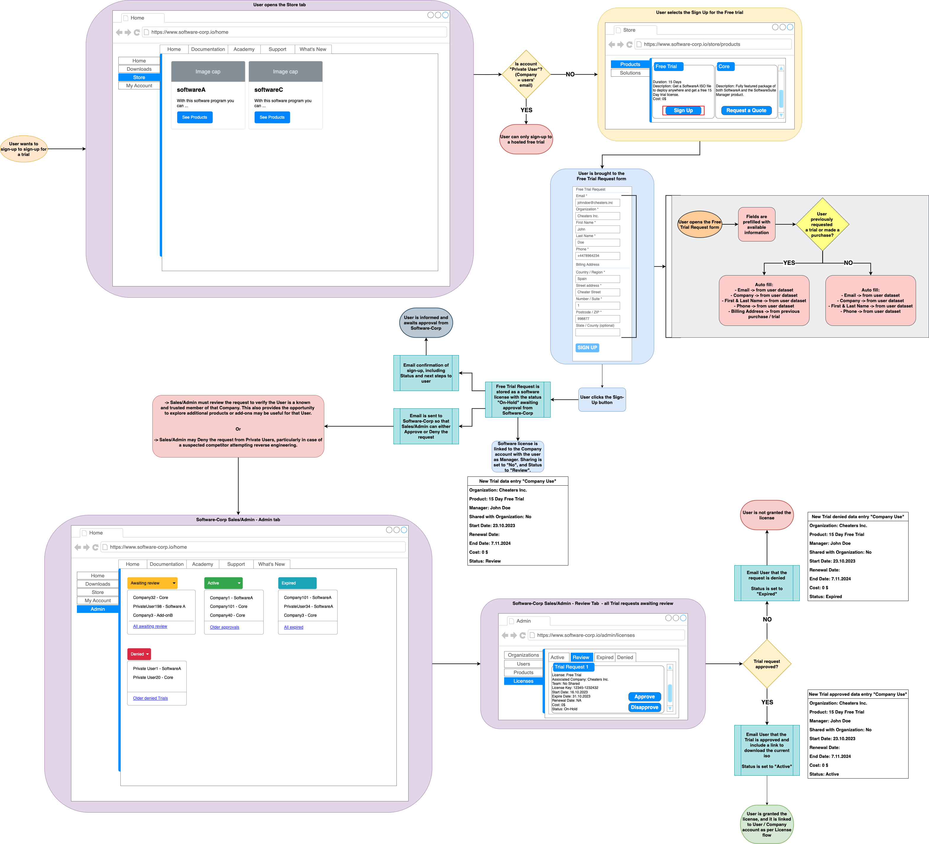
In the overview diagram on the first page, mock-ups of the main account webpages (tabs) and navigation are included but not documented in detail. The process flows for signing up and signing into a user account, as well as the process for requesting a quote or trial of a software license are drawn as one high-level step each. These are detailed in subsequent diagram pages.
These components are connected to the infrastructure systems that they need to interact with, but data requirements are not detailed in this overview - this is also drawn on subsequent diagram pages within this diagram file. Finally, notes that explain the purpose and limitations of the various components are placed around the overview.
Components detailed on other diagram pages are linked from this overview
Add more pages to your diagram
At the bottom of the drawing canvas next to the diagram page tabs, click + to add a new page within your diagram. Right-click on a diagram page tab or click on the ^ up arrow next to its name to rename or delete a page. You can also drag tabs around to change the order of the diagram pages.
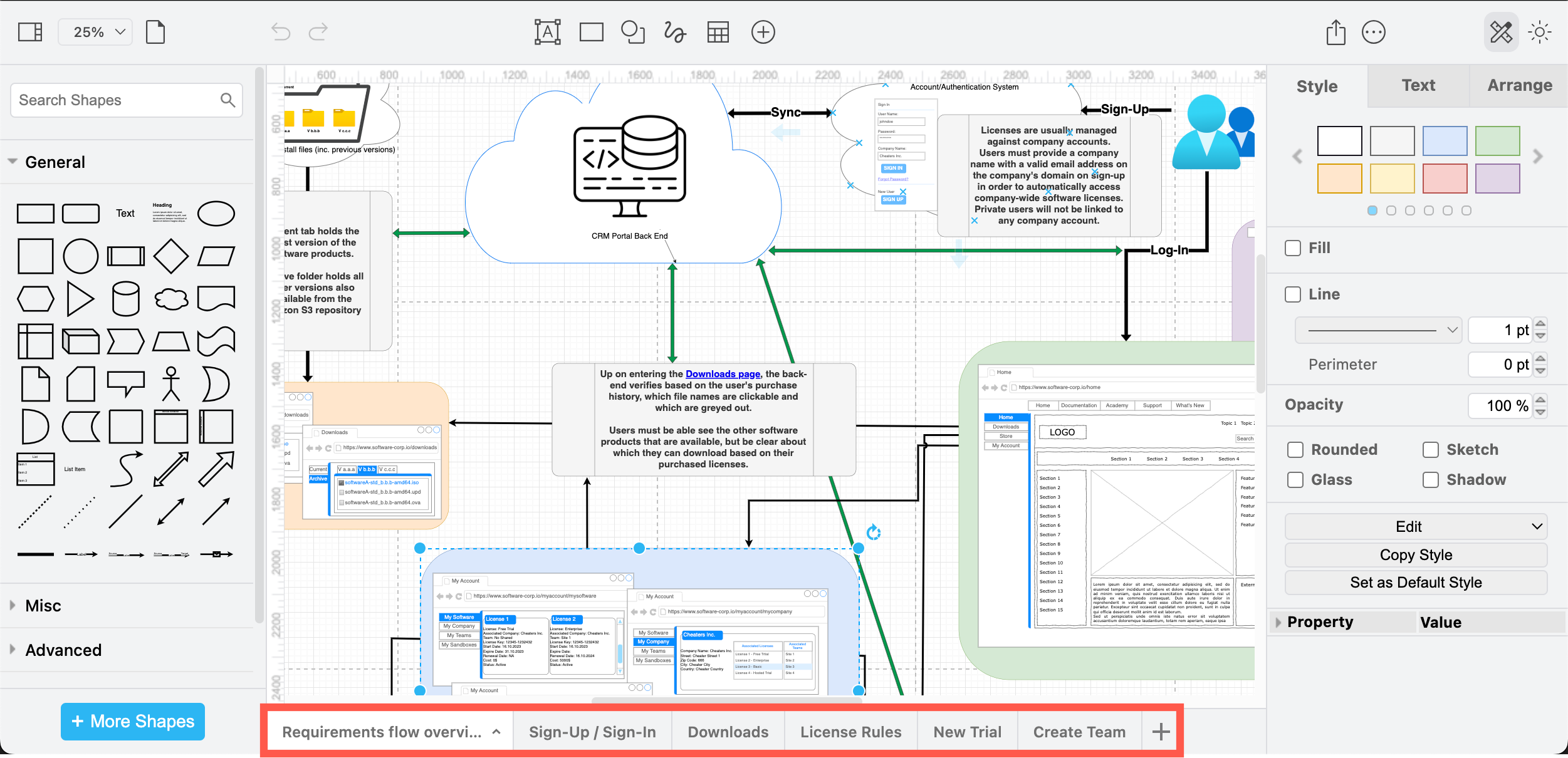
If you are using the Sketch online whiteboard editor theme, diagram pages are in a list in the lower right.
Link a shape to a different diagram page
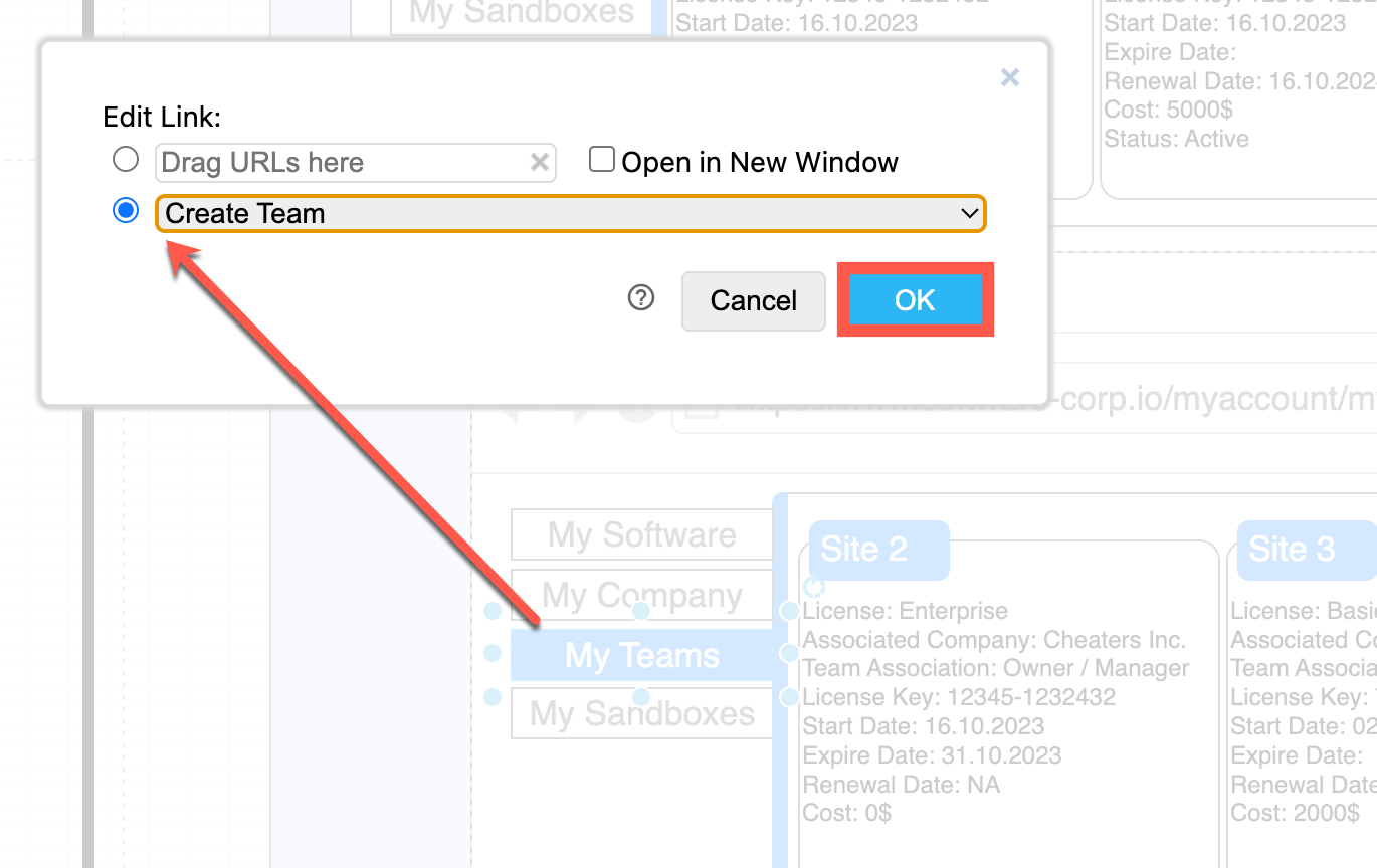
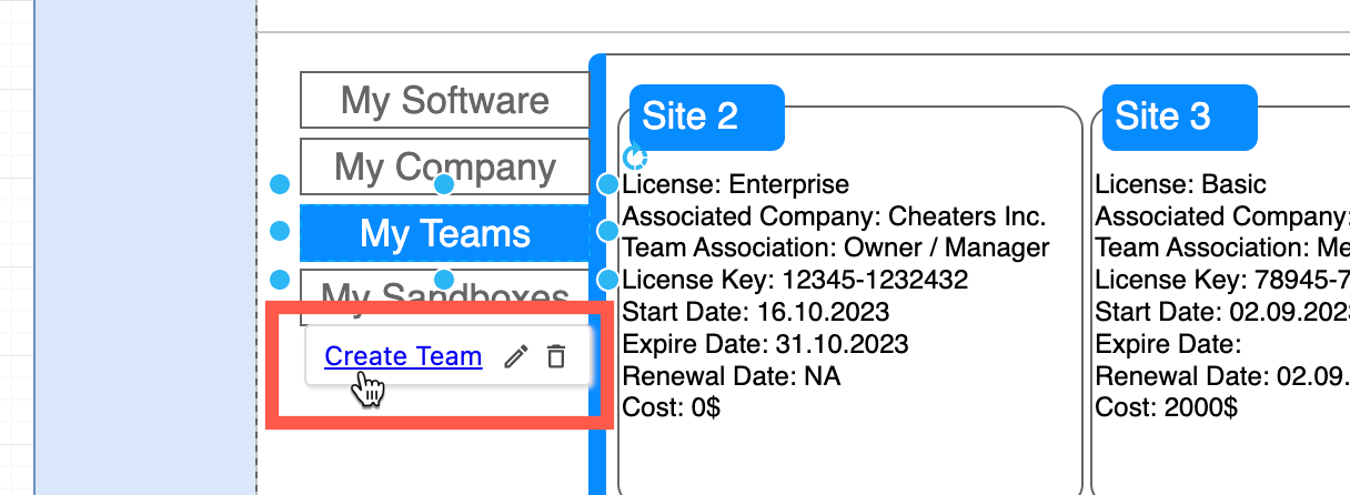
Right-click on a shape or connector or text and select Edit Link. Select the page from the list you want to link to and click OK. Then, hover over the shape with a link, a tooltip will appear. Click on this to go to the linked diagram page.
Draw sub-processes and sub-requirements on different pages
On the subsequent diagram pages, the engineer detailed the requirements and flows for the sign-in/sign-up process, the downloads page, licensing and trial request processes, and the team management process.
Tip: Click on any of these images to open the diagram page in the draw.io lightbox.
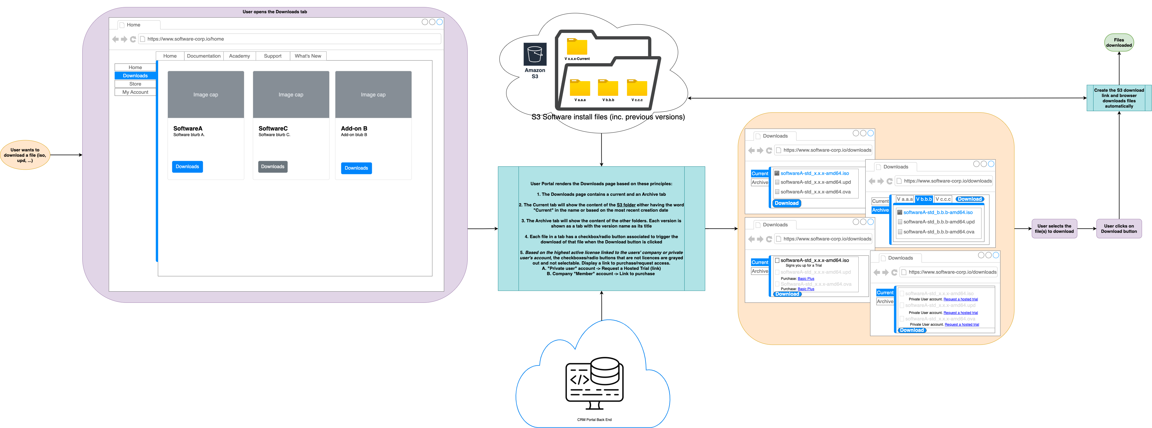
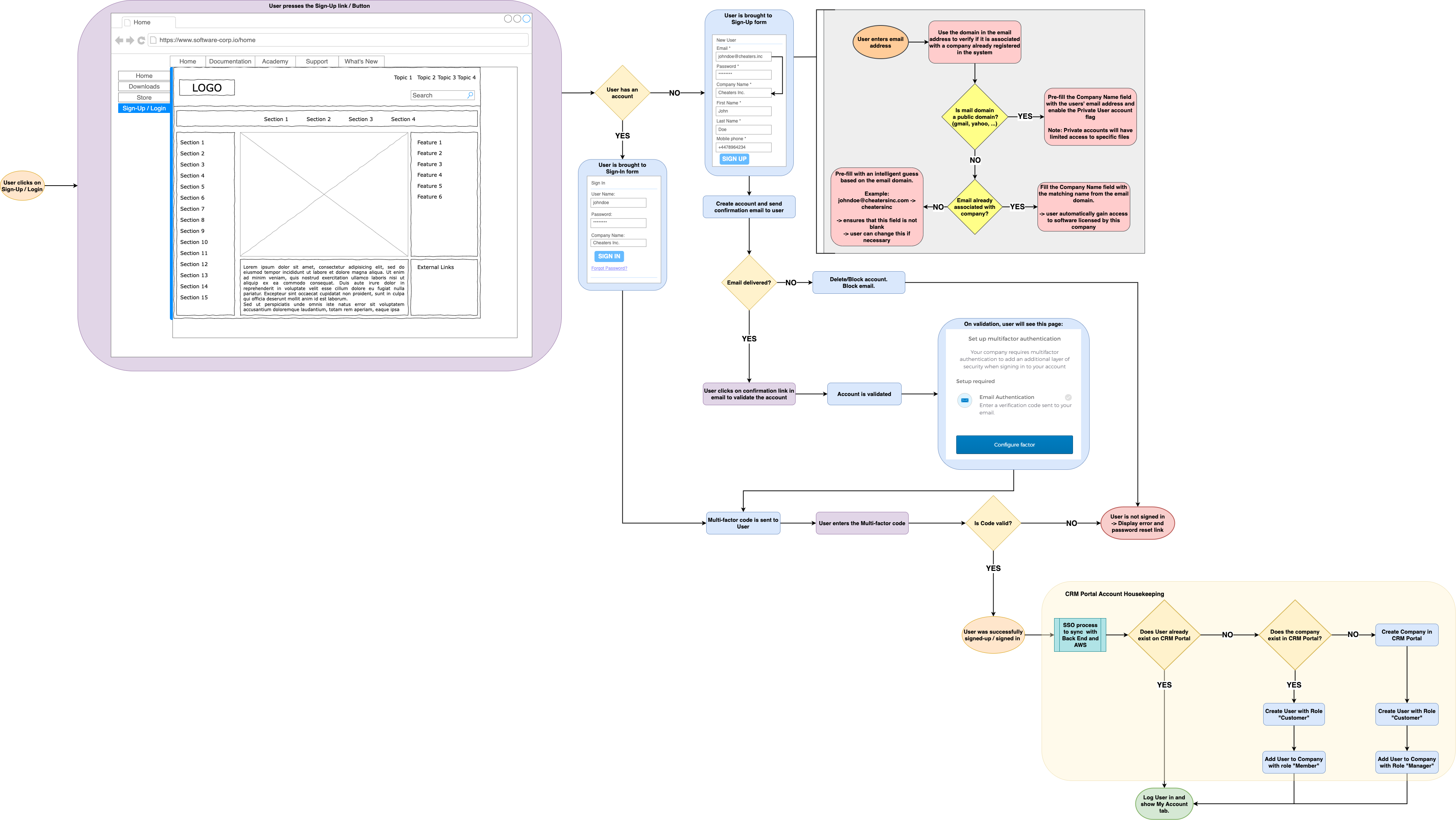
The processes, interfaces and rules for the sign-in/sign-up process and downloads webpage
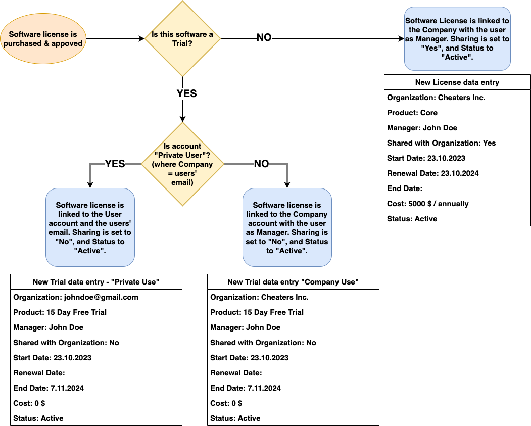
Licensing rules and data structures, and the process for requesting a new trial license
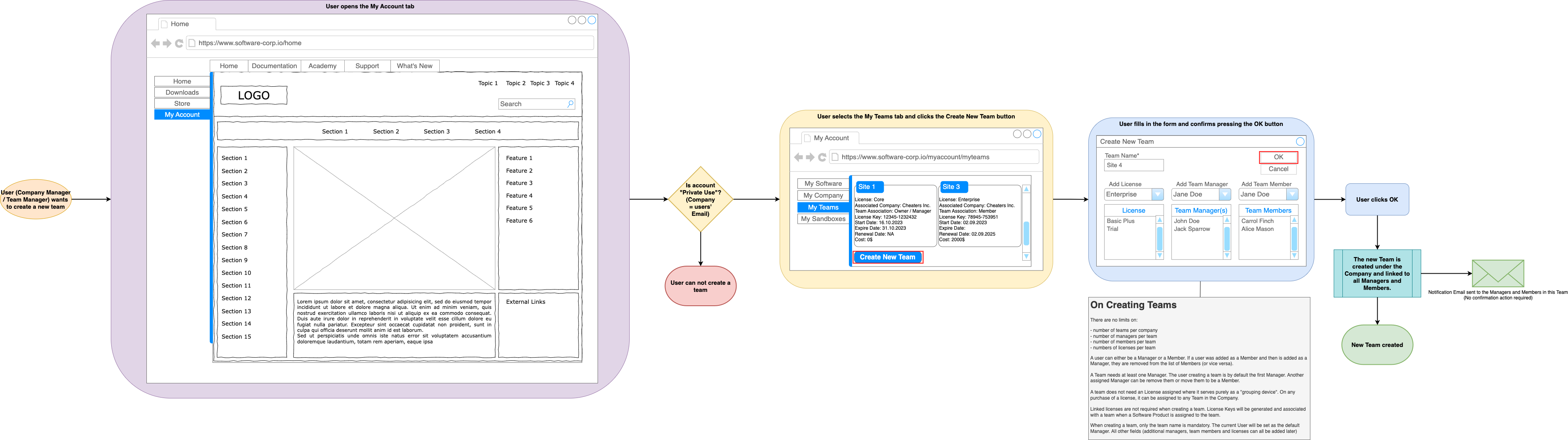
The process and interface mock-ups for adding or editing team within a company account by a manager user
Note: This is not a finished set of diagrams - there will likely be many more pages with additional details so that the external developers know exactly what they should be developing.
Process flows, interface mock-ups and data structures in one diagram
While the default General shape library likely has all the shapes and connectors you need for flows, you may find some other shape libraries useful to include various infrastructure systems with their recognised symbols. Shapes for interface mock-ups and data requirements are in several shape libraries.
Click on More Shapes at the bottom of the shape panel, then click on the checkboxes to enable the shape libraries you want to open, and click Apply. If you are using the Sketch editor theme, click on the + then select Shapes first.
The shape libraries you had enabled will appear in the shapes panel.
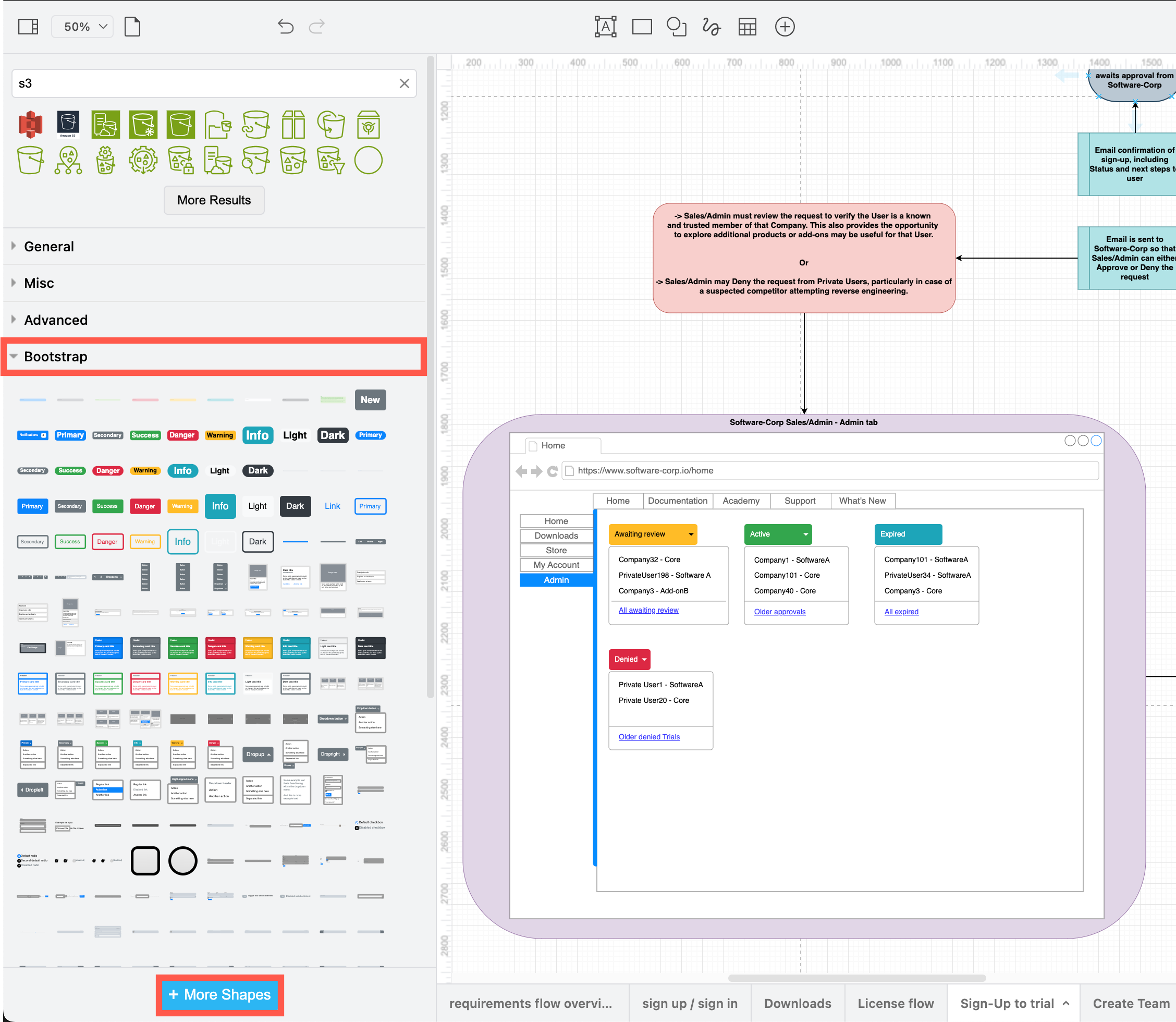
The Bootstrap shape library is useful when drawing software interface mock-ups
-
For more standardised flowchart shapes, open the BPMN and UML shape libraries.
-
For data structures, try the Entity Relation, UML and SysML shape libraries - entity relationship table shapes are best to create lists of data types.
-
Infrastructure components are mostly found in the Networking category. The Web Icons, Atlassian and Salesforce libraries may also be useful.
-
For mock-ups, see the Bootstrap, Android, iOS, Mockup and Material Design shape libraries.
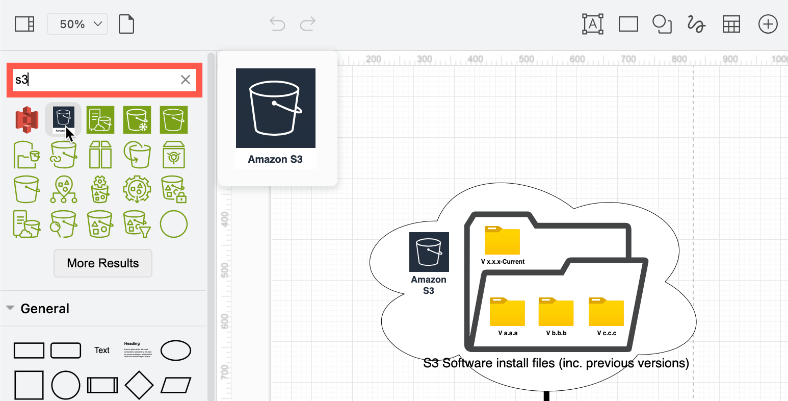
You can also search for shapes by their names in the top of the shapes panel. For example, search for S3 to find an appropriate Amazon AWS icon.
Use a template for interface mock-ups and system infrastructures
When you don’t need to specify an exact interface, there are several template diagrams for websites, apps and common infrastructure setups you can insert into your requirements flow.
Click Arrange > Insert > Template or + > Template in the toolbar to open the template manager. Check the Cloud and Wireframes categories for an appropriate template. Select a template diagram and click Insert to add it to the drawing canvas.
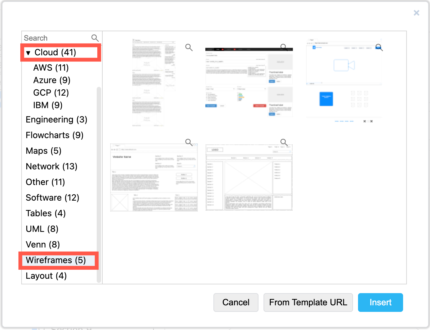
Tip: Click on the magnifying glass in the top right of any template to see a larger preview.
Working with large technical diagrams
By combining many different types of technical diagrams into one, the result can be large and complex diagrams on each page. draw.io provides many tools that make it easier to work with such diagrams.
Group shapes
In the example, the engineer added a coloured shape behind sections of the diagrams to show clearly that those components are tightly related. Group all tightly related shapes and connectors together so you can move them around the drawing canvas more easily.
- Select all the shapes, connectors and text you want to include.
- Right-click on one of the selected shapes and choose Group. Alternatively, press
Ctrl+GorCmd+Gto group them.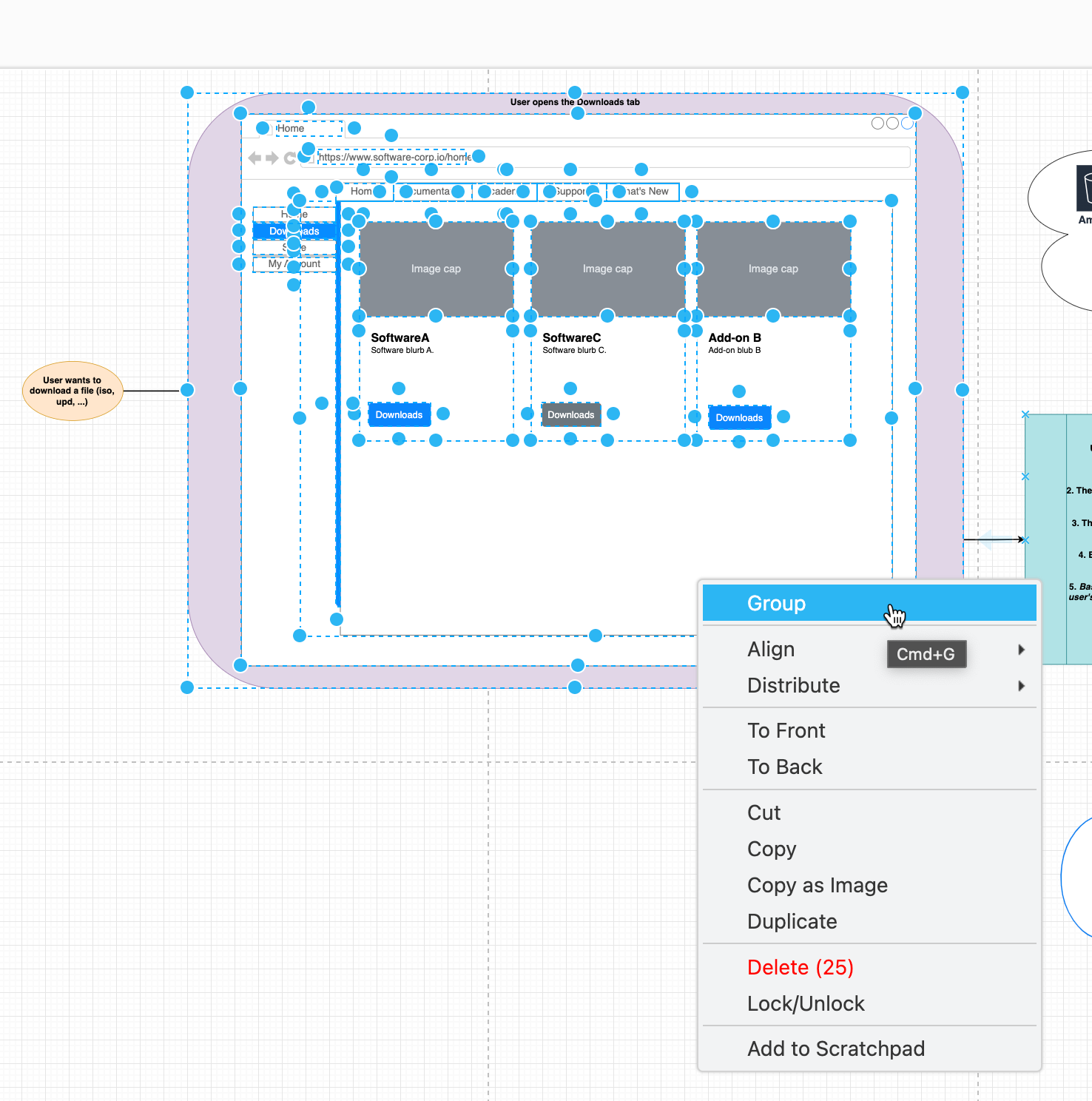
Add a new element to a group
- Drag a shape (or multiple selected shapes) over a group (or a container shape).
- Wait until the group outline turns purple - this means you will be adding the selected shapes to the group.
For example, dragging this website mock-up template and dropping into the container/group for the webpage navigation (Bootstrap shape library).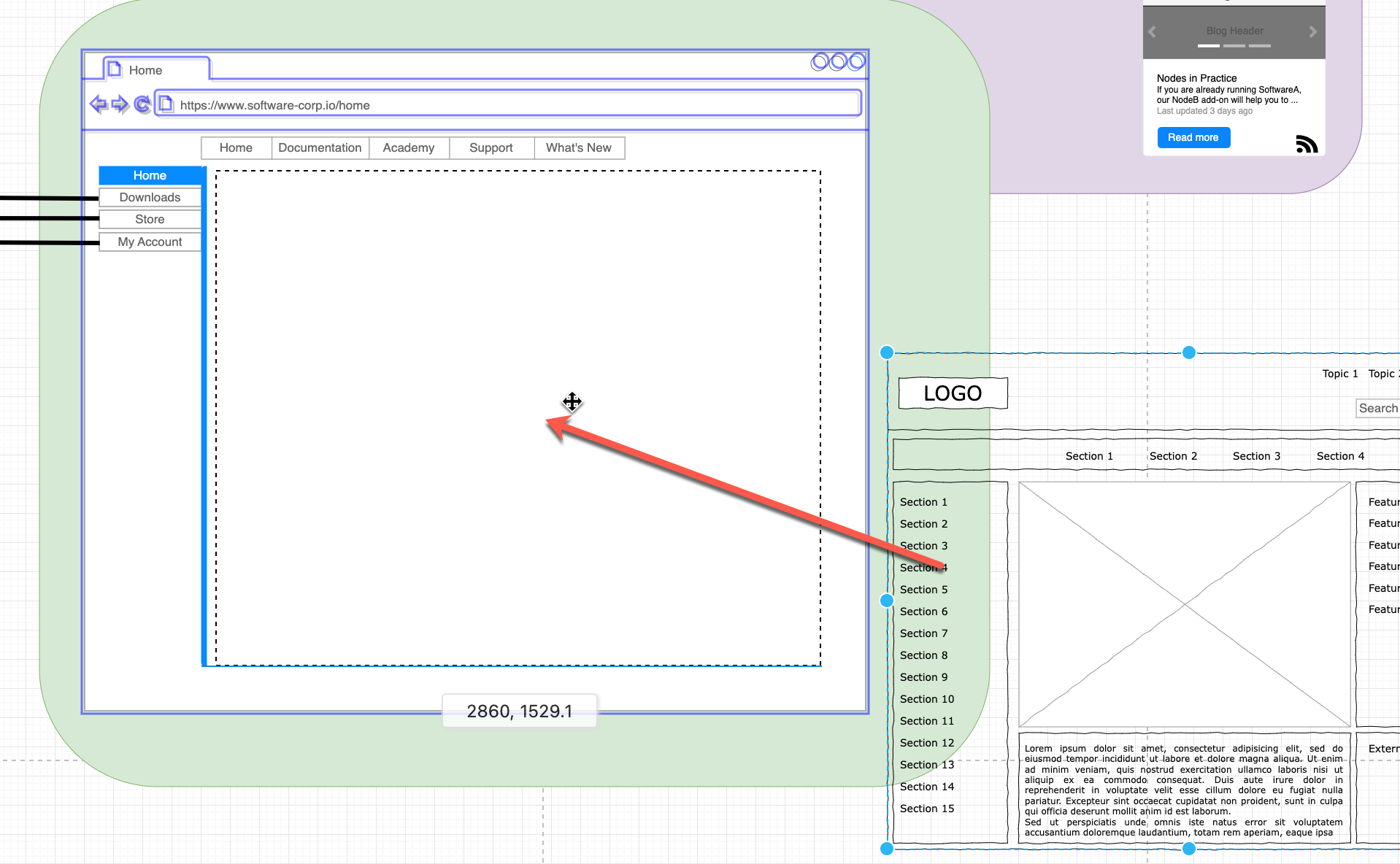
- The group will expand on the drawing canvas to fit the new shape(s) - you may need to resize the group afterwards.
Resize a group
Resizing a group may resize and shift that group’s shapes inside it as the editor tries to maintain relative proportions by default. If you don’t want this to happen, disable Resize Children in the group’s extended shape properties.
Ungroup shapes
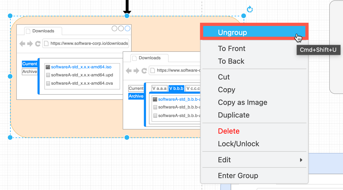
As groups may include container shapes that contain other shapes and groups within groups, it may be easier to ungroup all the shapes first, reposition and resize the additional related shapes, then group them all together again when finished.
Right-click on a group and select Ungroup, or press Ctrl+Shift+U on Windows, Cmd+Shift+U on macOS.
Find and replace text in diagrams
Press Ctrl+F on Windows, or Cmd+F on macOS to open the Find/Replace tool. Use this to update interface elements when you have changed their names to be consistent throughout the requirements flow diagrams. It’s also useful when obfuscating another’s diagram to use as an example, as in this case study.
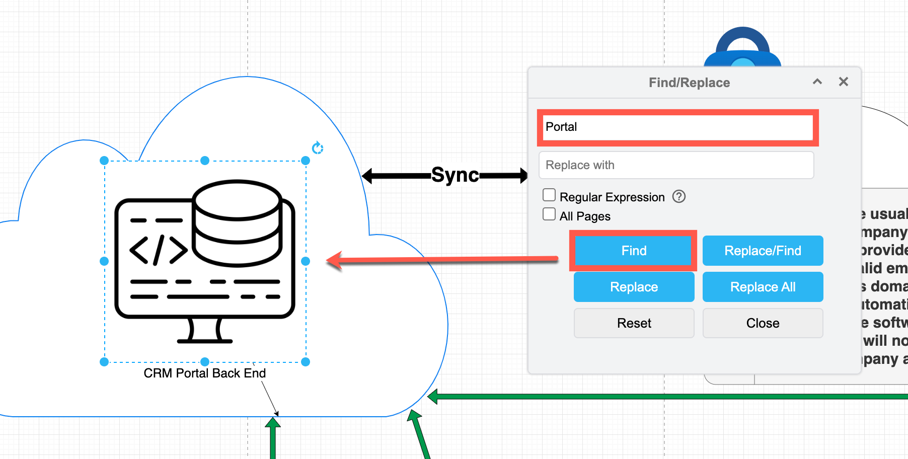
When you click Find, the first shape or connector on the diagram page that matches the string you entered will be selected. Click on Find again to move to and select the next matching shape or connector.
Note: Do this for each page in your multi-page diagram - it only finds text matches on the displayed diagram page.
More requirements diagram types
UML is commonly used to document software system requirements: use case diagrams, component diagrams, activity diagrams, sequence diagrams for processes, class diagrams for data structures, and state machine diagrams to document the trigger events in a process.
SysML has some similar diagrams, as well as the highly detailed block definition and parametric diagrams.
For a less software-engineering oriented approach, C4 models document systems and processes in four levels: from an abstract overview, and high-level technology choices, to system component details and data structures.
Network diagrams are used to document system infrastructures, and draw.io has shapes and templates for AWS, Cisco, Citrix, Google Cloud, IBM, Kubernetes and more.
Role responsibility diagrams are used to specify how exactly different user groups have different levels of access to systems, software and processes within those systems.
See our example diagram gallery for even more diagrams types.